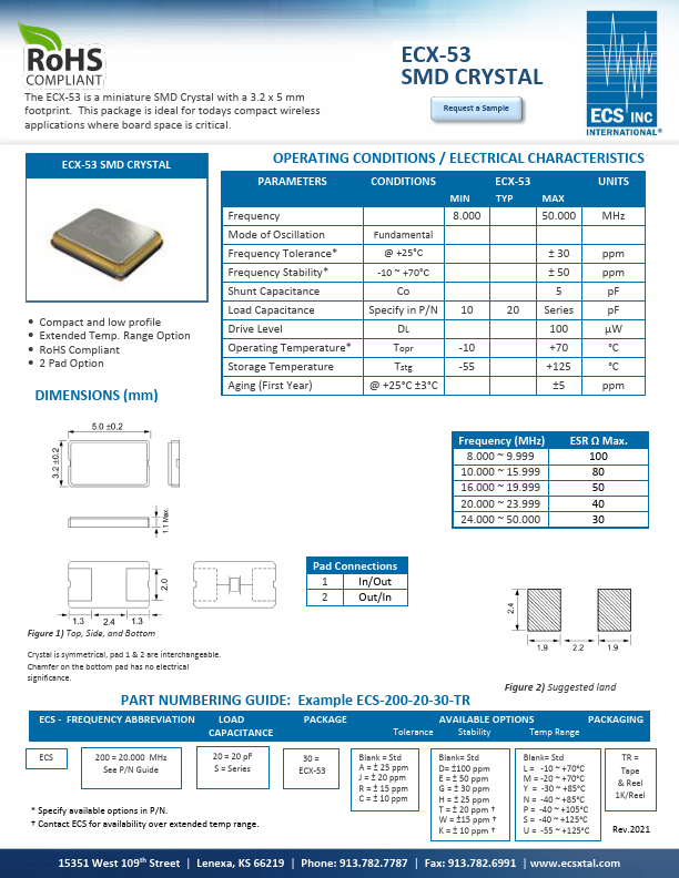
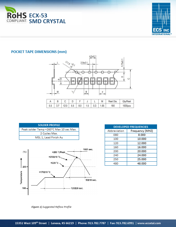
ELECTRICAL CHARACTERISTICS
PARAMETERS Frequency CONDITIONS MIN 8.000 ECX-53 TYP MAX 50.000 UNITS MHz Mode of Oscillation Fundamental Frequency Tolerance* @ +25°C ± 30 ppm Frequency Stability* -10 ~ +70°C ± 50 ppm Shunt Capacitance Co 5 pF Load Capacitance Specify in P/N 10 Drive Level DL Operating Temperature* Topr -10 Storage Temperature Tstg -55 Aging (First Year) @ +25°C ±3°C 20 Series pF 100 μW +70 °C +125 °C ±5 ppm Frequency (MHz) 8.000 ~ 9.999 10.000 ~ 15.999 16.000 ~ 19.999 20.000 ~ 23.999 24.000 ~ 50.000 ESR Ω Max. 100 80 50 40 30 Pad Connections 1 In/Out 2 Out/In Figure 1) Top, Side, and Bottom Crystal is symmetrical, pad 1 & 2 are interchangeable. Chamfer on the bottom pad has no electrical significance. PART NUMBERING GUIDE: Example ECS-200-20-30-TR Figure 2) Suggested land pattern ECS - FREQUENCY ABBREVIATION LOAD CAPACITANCE PACKAGE AVAILABLE OPTIONS PACKAGING Tolerance Stability Temp Range ECS 200 = 20.000 MHz See P/N Guide 20 = 20 pF S = Series * Specify available options in P/N. † Contact ECS for availability over extended temp range. ECS International