SZ60xx
SZ60xx is SURFACE MOUNT SILICON ZENER DIODES manufactured by EIC Semiconductor.
- Part of the SZ6010 comparator family.
- Part of the SZ6010 comparator family.
SZ603D
- SZ60D0
VZ : 3.3
- 200 Volts PD : 5 Watts
..
SURFACE MOUNT SILICON ZENER DIODES
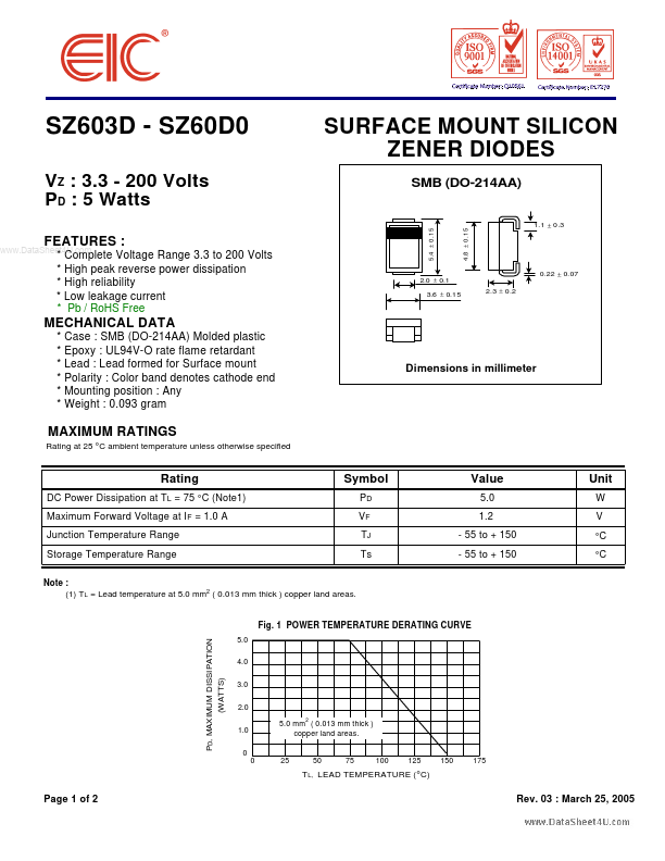
SMB (DO-214AA)
Features
:
- plete Voltage Range 3.3 to 200 Volts
- High peak reverse power dissipation
- High reliability
- Low leakage current
- Pb / RoHS Free
- -
- -
- - Case : SMB (DO-214AA) Molded plastic Epoxy : UL94V-O rate flame retardant Lead : Lead formed for Surface mount Polarity : Color band denotes cathode end Mounting position : Any Weight : 0.093 gram
4 .8 ± 0 .1 5
5 .4 ± 0 .15
1.1 ± 0 .3
2.0 ± 0.1 3.6 ± 0.1 5 2.3 ± 0.2
0.22 ± 0.07
MECHANICAL DATA
Dimensions in millimeter
MAXIMUM RATINGS
Rating at 25 °C ambient temperature unless otherwise specified
Rating...