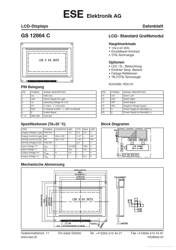
GND (0V) Power Supply for Logic Operating Voltage for LCD H: Data L: Instruction L: MPU to Module H: Module to MPU Enable Signal Data Bus PIN 15 16 17 18 19 20 Kontroller: KS0107 SYMBOL CS1 CS2 RST VEE A K SIGNAL
DESCRIPTION
Select Left Select Right Reset Signal Negative Voltage Supply Power Supply for Backlight (+) Power Supply for Backlight (–) Spezifikationen (TA=25 °C) ITEM SYMBOL CONDITION MIN. – Vdd = 5.0V Vee = 4.2V – H L H L 4.5 – – – Vss 2.4 – TYP. 5.0 1.47 1.46 8.2 – – – MAX. UNIT 5.5 – – – Vdd 0.8 – 0.4 V mA mA V V V V V Supply Voltage (Logic) Vdd-Vss Supply Current (Logic) Idd Driving Current (LCD) Driving Voltage (LCD) Input Voltage ”H” Input Voltage ”L” Output Voltage ”H” Output Voltage ”L” Iee Vdd-Vee VIH VIL VOH VOL Block Diagramm 0.8 Vdd – Mechanische Abmessung Grabenmattenstr. 11 CH-5608 Stetten Tel. +41(0)56 610 46 21 Fax +41(0)56 610 44 91 info@ese.ch Free Datasheet
This website uses cookies or similar technologies, to enhance your browsing experience and provide personalized recommendations. By continuing to use our website, you agree to our Privacy Policy