AN17850A
AN17850A is 70W x 1-Ch BTL Power Amplifier manufactured by Unknown Manufacturer.
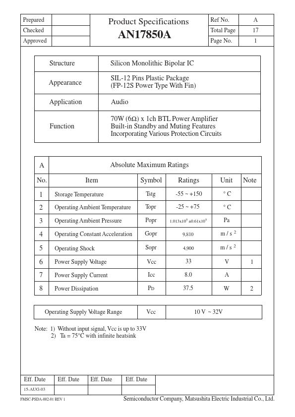
Features
Incorporating Various Protection Circuits
A No. 1 2 3 4 5 6 7 8 Item
Storage Temperature
Absolute Maximum Ratings Symbol
Tstg Topr Popr Gopr Sopr Vcc Icc PD
Ratings
-55 ~ +150 -25 ~ +75
1.013x10⁵ ±0.61x10⁵
Unit
°C °C Pa m/s m/s V A W
2 2
Note
Operating Ambient Temperature Operating Ambient Pressure Operating Constant Acceleration Operating Shock Power Supply V oltage Power Supply Current Power Dissipation
9,810 4,900
33 8.0 37.5
Operating Supply V oltage Range
Vcc
10 V ~ 32V
Note: 1) Without input signal, Vcc is up to 33V 2) Ta = 75°C with infinite heatsink
Eff. Date
15-AUG-03
Eff. Date
Eff. Date
Eff. Date Semiconductor pany, Matsushita Electric Industrial Co., Ltd.
FMSC-PSDA-002-01 REV 1
Prepared Checked Approved
Product Specifications
Ref No. Total Page Page No.
B-1 17 2
No. 1 2 3 4 5 6 7 8 9
Electrical Characteristics
Item
Quiescent Circuit Current Output Noise V oltage V oltage Gain Total Harmonic Distortion Maximum Output Power Output Offset V oltage Ripple Rejection Standby Current Muting Effects
(Unless otherwise specified, the ambient temperature is 25° C±2° C, Vcc=30V, frequency=1k Hz and RL=6Ω.)
Test Symbol Circuit.
Icq Vno Gvc THD Po V off RR 1 1 1 1 1 1 1 1...