Unknown Manufacturer GDM2004D
The internal operation is determined according to the signal from MPU, composed of read/write and data bus (Refer to Table7). When an MPU program with checking the busy flag (DB7) is made, it must be necessary 1/2 fuss for executing the next instruction by the falling edge of the “E” signal after the busy flag (DB7) goes to “LOW”.| Part No. | GDM2004D |
|---|---|
| Datasheet | GDM2004D Download |
| Manufacturer | Unknown Manufacturer |
| Description | LCD MODULE |
| Buy | Stock & Price |

FEATURES
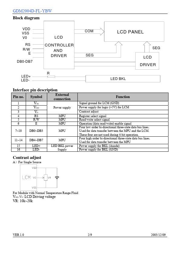
1. 5x8 dots 2. Built-in controller (S6A0069 or equivalent) 3. +5V power supply 4. 1/16 duty cycle 5. LED Backlight Outline dimension SPECIFICATIONS OF LCD MODULE Absolute maximum ratings Item Power voltage Input voltage Operating temperature range Storage temperature range Environmental Humidity Expected Life Time Symbol VDD-VSS VIN Top Tst Wide temperature range is available (operating/storage temperature as –20~+70/-30~+80 ) Unit: mm Standard 0VSS 0-10 - RH≤70% ≥50000 7.0 VDD +50 +60 Unit V ℃ H GDM2004D-FL-YBW Block diagram VDD VSS V0 RS R/W E DB0-DB7 LED+ LED- LCD CONTROLLER AND DRIVER COM SEG R LCD PANEL LED BKL SEG LCD DRIVER Interface pin description Pin no. 1 2 3 4 5 6 Symbol VSS VDD V0 RS R/W E External connection Power supply MPU MPU MPU 7~10 DB0~DB3 MPU 11~14 15 16 DB4~DB7 LED+ LED- MPU LED BKL power Supply Function Signal ground for LCM (GND) Power supply for logic (+5V) for LCM Contrast adjust Register select signal Read/write select signal Operation (data read/write) enable signal Four low order bi-directional three-state data bus lines.