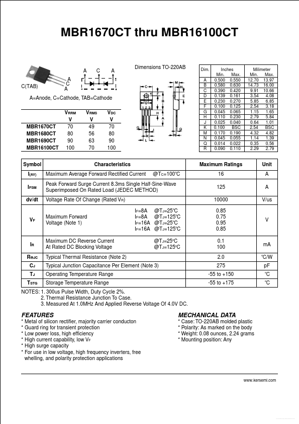
Datasheet4U Logo Datasheet4U.com

MBR16100CT Datasheet (mbr1670ct - Mbr16100ct)

Manufacturer: Unknown Manufacturer

Overview: MBR1670CT thru MBR16100CT Dimensions TO-220AB Dim. A B C D E F G H J K M N Q R Inches Min. Max. 0.500 0.550 0.580 0.630 0.390 0.420 0.139 0.161 0.230 0.270 0.100 0.125 0.045 0.065 0.110 0.230 0.025 0.040 0.100 BSC 0.170 0.190 0.045 0.055 0.014 0.022 0.090 0.110 Milimeter Min. Max. 12.70 13.97 14.73 16.00 9.91 10.66 3.54 4.08 5.85 6.85 2.54 3.18 1.15 1.65 2.79 5.84 0.64 1.01 2.54 BSC 4.32 4.82 1.14 1.39 0.35 0.56 2.29 2.79 A C(TAB) A C A C A A=Anode, C=Cathode, TAB=Cathode VRRM V 70 80 90 100 VRMS V 49 56 63 70 VDC V 70 80 90 100 MBR1670CT MBR1680CT MBR1690CT MBR16100CT Symbol I(AV) IFSM dv/dt Characteristics Maximum Average Forward Rectified Current @TC=100oC Maximum Ratings 16 125 10000 IF=8A IF=8A IF=16A IF=16A @TJ=25oC @TJ=125oC @TJ=25oC @TJ=125oC @TJ=25oC @TJ=125oC 0.85 0.75 0.95 0.85 0.1 100 2.0 275 -55 to +150 -55 to +175 Unit A A V/us Peak Forward Surge Current 8.3ms Single Half-Sine-Wave Superimposed On Rated Load (JEDEC METHOD) Voltage Rate Of Change (Rated VR) Maximum Forward Voltage (Note 1) VF V IR ROJC CJ TJ TSTG Maximum DC Reverse Current At Rated DC Blocking Voltage Typical Thermal Resistance (Note 2) mA o C/W pF o o Typical Junction Capacitance Per Element (Note 3) Operating Temperature Range Storage Temperature Range C C NOTES: 1. 300us Pulse Width, Duty Cycle 2%. 2. Thermal Resistance Junction To Case. 3. Measured At 1.0MHz And Applied Reverse Voltage Of 4.0V DC.

This datasheet includes multiple variants, all published together in a single manufacturer document.

Key Features

  • Metal of silicon rectifier, majority carrier conducton.
  • Guard ring for transient protection.
  • Low power loss, high efficiency.
  • High current capability, low VF.
  • High surge capacity.
  • For use in low voltage, high frequency inverters, free whelling, and polarity protection.

MBR16100CT Distributor