SF1007G
SF1007G is 10.0 AMPS. Glass Passivated Super Fast Rectifiers manufactured by Unknown Manufacturer.
- Part of the SF1001G comparator family.
- Part of the SF1001G comparator family.
Features
Low forward voltage drop High current capability High reliability High surge current capability
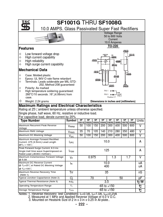
TO-220
Mechanical Data
Case: Molded plastic Epoxy: UL 94V-O rate flame retardant Terminals: Leads solderable per MIL-STD202, Method 208 guaranteed Polarity: As marked High temperature soldering guaranteed: o 260 C/10 seconds .16”,(4.06mm) from case. Weight: 2.24 grams
PIN 1 PIN 3 Positive CT CASE PIN 2
Dimensions in inches and (millimeters)
Maximum Ratings and Electrical Characteristics
Rating at 25℃ambient temperature unless otherwise specified. Single phase, half wave, 60 Hz, resistive or inductive load. For capacitive load, derate current by 20% SF SF SF Symbol SF Type Number
Maximum Recurrent Peak Reverse Voltage Maximum RMS Voltage Maximum DC Blocking Voltage Maximum Average Forward Rectified Current .375 (9.5mm) Lead Length @TC = 100℃ Peak Forward Surge Current, 8.3 ms Single Half Sine-wave Superimposed on Rated Load (JEDEC method ) Maximum Instantaneous Forward Voltage @ 5.0A Maximum DC Reverse Current @ TA=25℃at Rated DC Blocking Voltage @ TA=100℃ Maximum Reverse Recovery Time (Note 1) Typical Junction Capacitance (Note 2) Typical Thermal Resistance (Note 3)
SF SF SF SF 1001G 1002G 1003G 1004G 1005G 1006G 1007G 1008G
Units V V V A A
VRRM VRMS VDC I(AV) IFSM VF IR
50 35 50
100 150 200 300 400 500 600 70 105 140 210 280 350 480 100 150 200 300 400 500 600
10.0 125 0.975 10.0 400 35 70 50 1.3 1.7
V u A u A n S p F ℃/W ℃ ℃
Trr Cj
RθJC
3.5 Operating Temperature Range TJ -65 to +150 Storage Temperature Range TSTG -65 to +150 Notes: 1. Reverse Recovery Test Conditions: IF=0.5A, IR=1.0A, IRR=0.25A 2. Measured at 1 MHz and Applied Reverse Voltage of 4.0 V D.C. 3. Mounted on Heatsink Size of 2 in x 3 in x 0.25 in Al-plate..
- 222
- RATINGS AND CHARACTERISTIC CURVES (SF1001G THRU SF1008G)
FIG.1- REVERSE RECOVERY TIME CHARACTERISTIC AND TEST CIRCUIT DIAGRAM
50W NONINDUCTIVE 10W NONINDUCTIVE +0.5A (-) DUT (+) 50Vdc (approx) (-) PULSE GENERATOR (NOTE 2) 1W...