Datasheet4U Logo Datasheet4U.com

THB6128 - Motor Driver

Description

of functions 9-1) Stand-by function When ST/VCC pin is at low levels, the IC enters stand-by mode, all logic is reset and output is turned OFF.

When ST/VCC pin is at high levels, the stand-by mode is released.

9-2) Step pin function CLK pin step signal input allows advancing excitation step.

Features

  • 1 channel PWM current control stepping motor driver BiCDMOS process IC Output on-resistance( High side 0.3 Ω, Low side 0.25 Ω, Total 0.55 Ω; Ta = 25°C, Io = 2.0 A) 2, 1-2, W1-2, 2W1-2, 4W1-2, 8W1-2, 16W1-2, 32W1-2 phase excitation are selectable Advance the excitation step with the only step signal input.
  • Available forward reverse control.
  • Iomax=2.2A.
  • Over current protection circuit Thermal shutdown circuit Input pull down resistanc.

📥 Download Datasheet

Datasheet preview – THB6128

Datasheet Details

Part number THB6128
Manufacturer ETC
File Size 425.19 KB
Description Motor Driver
Datasheet download datasheet THB6128 Datasheet
Additional preview pages of the THB6128 datasheet.
Other Datasheets by ETC

Full PDF Text Transcription

Click to expand full text
THB6128 Development Specification Proposal 
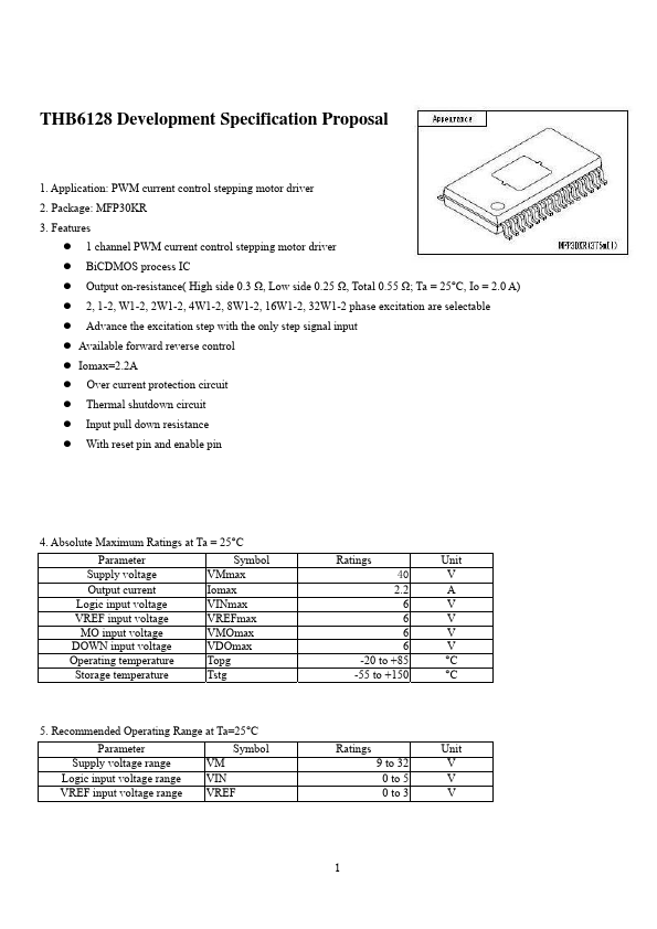
1. Application: PWM current control stepping motor driver 2. Package: MFP30KR 3. Features      1 channel PWM current control stepping motor driver BiCDMOS process IC Output on-resistance( High side 0.3 Ω, Low side 0.25 Ω, Total 0.55 Ω; Ta = 25°C, Io = 2.0 A) 2, 1-2, W1-2, 2W1-2, 4W1-2, 8W1-2, 16W1-2, 32W1-2 phase excitation are selectable Advance the excitation step with the only step signal input  Available forward reverse control  Iomax=2.2A     Over current protection circuit Thermal shutdown circuit Input pull down resistance With reset pin and enable pin 4.
Published: |