XR-T56L85
XR-T56L85 is Low Power PCM Line Interface manufactured by Exar.
DESCRIPTION
The XR-T56L85 is a PCM line interface chip. It consists of both transmit and receive circuitry in a DIL 18 pin package. The maximum bit rate the chip can handle is 2.048 Mbps and the signal level to the received can be ORDERING INFORMATION
Part No. XR-T56L85N XR-T56L85D attenuated by 10d B of cable loss at half the bit rate. Total current consumption is between 12-16m A at +5V.
Package 18 Lead 300 Mil CDIP 18 Lead 300 Mil JEDEC SOIC
Operating Temperature Range -40°C to +85°C -40°C to +85°C
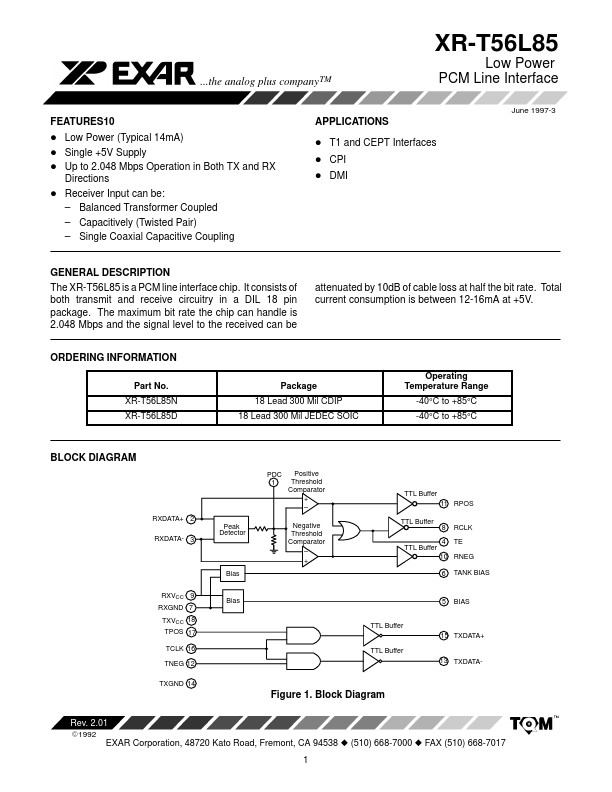
BLOCK DIAGRAM
PDC 1 Positive Threshold parator +
- Negative Threshold parator
- +
TTL Buffer 11 RPOS TTL Buffer 8 4 RCLK TE
RXDATA+ 2 RXDATA- 3 Peak Detector
TTL Buffer
10 RNEG 6 TANK BIAS
Bias RXVCC 9 RXGND 7 TXVCC 18 TPOS 17 TCLK 16 TNEG 12 TXGND 14 TTL Buffer TTL Buffer
Bias
BIAS
15 TXDATA+
13 TXDATA-
Figure 1. Block Diagram
Rev. 2.01
E1992
EXAR Corporation, 48720 Kato Road, Fremont, CA 94538 z (510) 668-7000 z FAX (510) 668-7017 1
PIN CONFIGURATION
PDC RXDATA+ RXDATATE BIAS TANK BIAS RXGND RCLK RXVCC
1 2 3 4 5 6 7 8 9 18 17 16 15 14 13 12 11 10
TXVCC TPOS TCLK TXDATA+ TXGND TXDATATNEG RPOS RNEG
PDC RXDATA+ RXDATATE BIAS TANK BIAS RXGND RCLK RXVCC
1 2 3 4 5 6 7 8 9
18 17 16 15 14 13 12 11 10
TXVCC TPOS TCLK TXDATA+ TXGND TXDATATNEG RPOS RNEG
18 Lead CDIP (0.300”)
18 Lead SOIC (Jedec, 0.300”)
PIN DESCRIPTION
Pin # 1 2 Symbol PDC RXDATA+ I Type Description
Peak Detector Capacitor. This pin should be connected to a 0.1µF capacitor Receive Analog Input Positive. The AMI signal received from the line is applied at this and the RX DATA(-) pin. Data and clock from the signal applied at these two pins recovered and output on the RPOS, RNEG, and RCLK pins, respectively. Receive Analog Input Negative. See the description for RX DATA(+). LC Tank Excitation Output. This output connects to one side of the tank circuitry. Bias. This pin should be tied to ground through a 0.1µF capacitor. Tank Reference. The tank circuitry is biased via this...