XR19L210
XR19L210 is SINGLE CHANNEL INTEGRATED UART AND RS-232 TRANSCEIVER manufactured by Exar.
DESCRIPTION
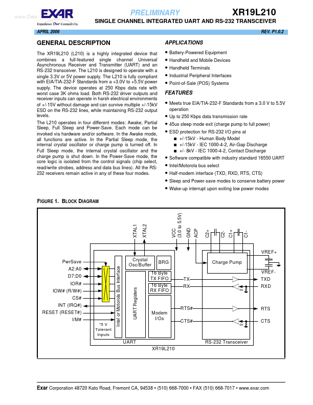
The XR19L210 (L210) is a highly integrated device that bines a full-featured single channel Universal Asynchronous Receiver and Transmitter (UART) and an RS-232 transceiver. The L210 is designed to operate with a single 3.3V or 5V power supply. The L210 is fully pliant with EIA/TIA-232-F Standards from a +3.0V to +5.5V power supply. The device operates at 250 Kbps data rate with worst case 3K ohms load. Both RS-232 driver outputs and receiver inputs can operate in harsh electrical environments of +/-15V without damage and can survive multiple +/-15k V ESD on the RS-232 lines, while maintaining RS-232 output levels. The L210 operates in four different modes: Awake, Partial Sleep, Full Sleep and Power-Save. Each mode can be invoked via hardware and/or software. In the Awake mode, all functions are active. In the Partial Sleep mode, the internal crystal oscillator or charge pump is turned off. In Full Sleep mode, the internal crystal oscillator and the charge pump is shut down. In the Power-Save mode, the core logic is isolated from the control signals (chip select, read/write strobes, address and data bus lines). All the RS232 receivers remain active in any of these four modes.
APPLICATIONS
- Battery-Powered Equipment
- Handheld and Mobile Devices
- Handheld Terminals
- Industrial Peripheral Interfaces
- Point-of-Sale (POS) Systems
FEATURES
- Meets true EIA/TIA-232-F Standards from a 3.0 V to 5.5V operation
- Up to 250 Kbps data transmission rate
- 45us sleep mode exit (charge pump to full power)
- ESD protection for RS-232 I/O pins at
- -
- +/-15k V
- Human Body Model +/-15k V
- IEC 1000-4-2, Air-Gap Discharge +/- 8k V
- IEC 1000-4-2, Contact Discharge
- Software patible with industry standard 16550 UART
- Intel/Motorola bus select
- Half-modem interface (TXD, RXD, RTS, CTS)
- Sleep and Power-save modes to conserve battery power
- Wake-up interrupt upon exiting low power modes
FIGURE 1. BLOCK DIAGRAM
VCC (3.0 to 5.5V)
XTAL1
XTAL2
C2+
C1+...