DESCRIPTION
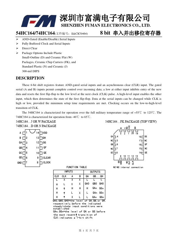
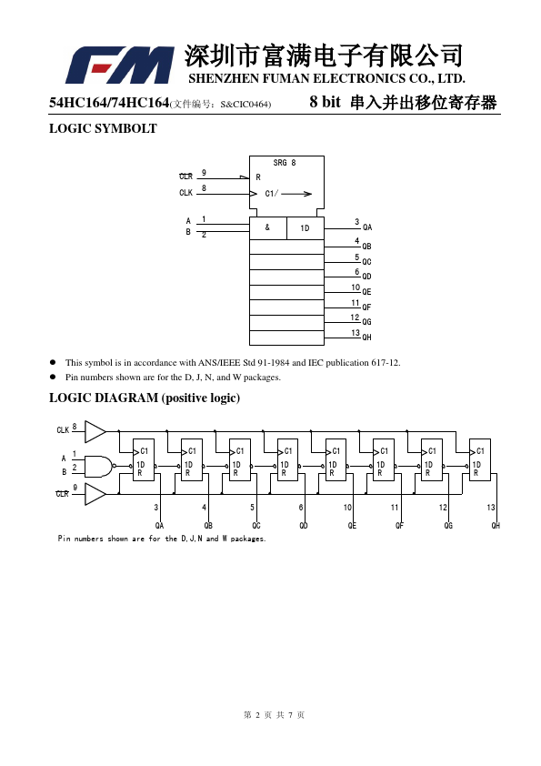
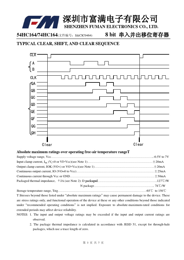
These 8-bit shift registers feature AND-gated serial inputs and an asynchronous clear (CLR) input. The gated serial (A and B) inputs permit complete control over incoming data; a low at either input inhibits entry of the new data and resets the first flip-flop to the low level at the next clock (CLK) pulse. A high-level input enables the other input, which then determines the state of the f1irst flip-flop. Data at the serial inputs can be ch2anged while CLK is high or low, provided the minimum setup time requirements are met. Clocking occurs on the low-to-high-level transition of CLK. 1 2 54HC164…J OR W PACKAGE 54HC164…FK PACKAGE (TOP VIEW) 74HC164…D OR N PACDKAGE QD GND B A NC NC CLK VCC CLR QH A1 14 VDD B2 13 QH D QA 3 12 QG QB 4 11 QF QC 5 QD 6 10 QE 9 CLEAR D 3 2 1 20 19 QA 4 18 QG NC 5 17 NC QB 6 16 QF NC 7 15 NC QC 8 14 QE 9 10 11 12 13 GND 7 8 CLOCK FUNCTION TABLE NC-NO internal connection INPUTS OUTPUTS CLR CLK A B QA QB...QH C L X X X LLL H L X X QA0 QB0 QH0 H C H... FUMAN ELECTRONICS