DM74ALS174
DM74ALS174 is Hex/Quad D-Type Flip-Flops manufactured by Fairchild Semiconductor.
Description
These positive-edge-triggered flip-flops utilize TTL circuitry to implement D-type flip-flop logic. Both have an asynchronous clear input, and the quad (DM74ALS175) version features plementary outputs from each flip-flop. Information at the D inputs meeting the setup time requirements is transferred to the Q outputs on the positive-going edge of the clock pulse. Clock triggering occurs at a particular voltage level and is not directly related to the transition time of the positive-going pulse. When the clock input is at either the HIGH or LOW level, the D input signal has no effect at the output.
Features s Advanced oxide-isolated ion-implanted Schottky TTL process s Pin and functional patible with LS family counterpart s Typical clock frequency maximum is 80 MHz s Switching performance guaranteed over full temperature and VCC supply range
Ordering Code:
Ordering Code DM74ALS174M DM74ALS174SJ DM74ALS174N DM74ALS175M DM74ALS175SJ DM74ALS175N Package Number M16A M16D N16E M16A M16D N16E Package Description
16-Lead Small Outline Integrated Circuit (SOIC), JEDEC MS-012, 0.150 Narrow 16-Lead Small Outline Package (SOP), EIAJ TYPE II, 5.3mm Wide 16-Lead Plastic Dual-In-Line Package (PDIP), JEDEC MS-001, 0.300 Wide 16-Lead Small Outline Integrated Circuit (SOIC), JEDEC MS-012, 0.150 Narrow 16-Lead Small Outline Package (SOP), EIAJ TYPE II, 5.3mm Wide 16-Lead Plastic Dual-In-Line Package (PDIP), JEDEC MS-001, 0.300 Wide
Devices also available in Tape and Reel. Specify by appending the suffix letter “X” to the ordering code.
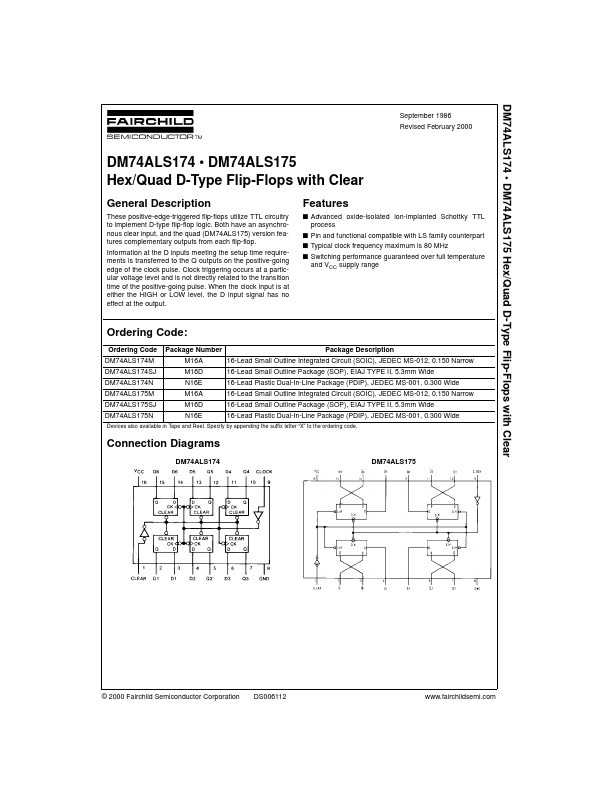
Connection Diagrams
DM74ALS174 DM74ALS175
© 2000 Fairchild Semiconductor Corporation
DS006112
.fairchildsemi.
- DM74ALS175
Function Table
Inputs Clear L H H H Clock X ↑ ↑ L D X H L X Q L H L Q0 Outputs Q (Note 1) H L H Q0
H = HIGH Level (steady state) L = LOW Level (steady state) X = Don’t Care ↑ = Transition from LOW-to-HIGH Level Q0 = the level of Q before the indicated steady-state input conditions were established...