74HC4538
Description
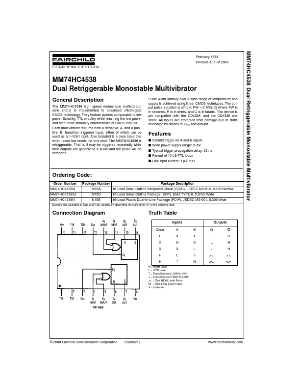
The MM74HC4538 high speed monostable multivibrator (one shots) is implemented in advanced silicon-gate CMOS technology.
Key Features
- Specify by appending the suffix letter “X” to the ordering code
- MM74HC4538 Block Diagrams Note: Pin 1 and Pin 15 must be hard-wired to GND
- Logic Diagram .fairchildsemi
- 2 MM74HC4538 Timing Diagram Circuit Operation The MM74HC4538 operates as follows (refer to logic diagram)
- In the quiescent state, the external timing capacitor, CX, is charged to VCC
- When a trigger occurs, the Q output goes HIGH and CX discharges quickly to the lower reference voltage (VREF Lower = 1/3 VCC )
- The following, more detailed description of the circuit operation refers to both the logic diagram and the timing diagram
- Thus the Q output (pin 6 or 10) of the monostable multivibrator is LOW (#2, timing diagram)
- The output of the trigger-control circuit is LOW (#3), and transistors M1, M2, and M3 are turned off
- The external timing capacitor, CX, is charged to VCC (#4), and the upper reference circuit has a LOW output (#5)