33999
33999 is 16-Output Switch manufactured by Freescale Semiconductor.
features that reduces the MCU’s fault management burden. Features
- Designed to Operate 5.0 V < VPWR < 27 V
- 24-Bit SPI for Control and Fault reporting, 3.3 V/5.0 V patible
- Outputs Are Current Limited (0.9 A to 2.5 A) to Drive Incandescent Lamps
- Output Voltage Clamp of +50 V During Inductive Switching
- On/Off Control of Open Load Detect Current (LED Application)
- VPWR Standby Current < 10 µA
- RDS(ON) of 0.55 Ω at 25°C Typical
- -
- -
- Independent Overtemperature Protection Output Selectable for PWM Control Output ON Short-to-VBAT and OFF Short-to-Ground/Open Detection 54-Pin Exposed Pad Package for Thermal Performance Pb-Free Packaging Designated by Suffix Code EK
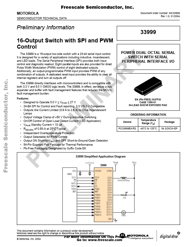
Simplified Application Diagram 33999 Simplified Application Diagram 33999 Simplified Application Diagram
3.3 V/5.0 V VPWR VBAT
POWER DUAL OCTAL SERIAL SWITCH WITH SERIAL PERIPHERAL INTERFACE I/O
Freescale Semiconductor, Inc...
EK (Pb-FREE) SUFFIX CASE 1390-01 54-LEAD SOICW EXPOSED PAD
ORDERING INFORMATION
Device PC33999EK/R2 Temperature Range (TA) -40°C to 125°C Package 54 SOICW-EP
VDD MCU SCLK CS MISO MOSI PWM RST SCLK CS SI SO PWM RST PWM0 PWM1 PWM6 PWM7 PWM8 PWM9 PWM14 PWM15 OUT0 OUT1 OUT2 OUT3 OUT4 OUT5 OUT6 OUT7 OUT8 OUT9 OUT10 OUT11 OUT12 OUT13 OUT14 OUT15 GND Solenoid/Relay SOPWR VPWR
Lamp
This document contains information on a product under development. Motorola reserves the right to change or discontinue this product without notice. © Motorola, Inc. 2004
For More Information On This Product, Go to: .freescale. http://../
Freescale Semiconductor, Inc.
VPWR VDD Overvoltage Detect OVD VDD RB SFPDB SFL SCLK CSB SI SO CSI CSBI
8 VDD Bias Gate Control OUT0 2 50 V OUT1- OUT15: 3, 6, 7, 21, 22, 25, 26, 29, 30, 33, 34, 48, 49, 52, 53
Voltage Regulator GE OT SF OF
PWM 50 RST 47 CS 23
10 µA 25 µA 10 µA Input Buffers 10 µA 10 µA Serial D/O Line Driver
To Gates 1o t 15
VRef Open Load Detect Enable ILIMIT 50 µA RS
Freescale Semiconductor, Inc...
SCLK 20 SI 32 SO 35...