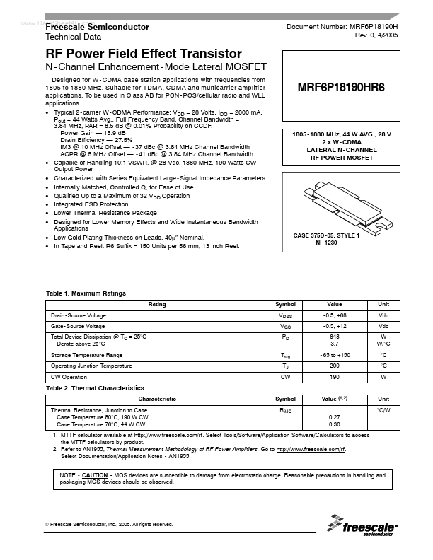
MRF6P18190HR6
..
Freescale Semiconductor Technical Data
Document Number: MRF6P18190H Rev. 0, 4/2005
RF Power Field Effect Transistor
- Channel Enhancement
- Mode Lateral MOSFET
Designed for W
- CDMA base station applications with frequencies from 1805 to 1880 MHz. Suitable for TDMA, CDMA and multicarrier amplifier applications. To be used in Class AB for PCN
- PCS/cellular radio and WLL applications.
- Typical 2
- carrier W
- CDMA Performance: VDD = 28 Volts, IDQ = 2000 m A, Pout = 44 Watts Avg., Full Frequency Band, Channel Bandwidth = 3.84 MHz, PAR = 8.5 d B @ 0.01% Probability on CCDF. Power Gain
- 15.9 d B Drain Efficiency
- 27.5% IM3 @ 10 MHz Offset
- - 37 d Bc @ 3.84 MHz Channel Bandwidth ACPR @ 5 MHz Offset
- - 41 d Bc @ 3.84 MHz Channel Bandwidth
- Capable of Handling 10:1 VSWR, @ 28 Vdc, 1880 MHz, 190 Watts CW Output Power
- Characterized with Series Equivalent Large
- Signal Impedance Parameters
- Internally Matched, Controlled Q, for Ease of Use
- Qualified Up to a Maximum of 32 VDD...