MRF8S18120HSR3 Overview
Key Specifications
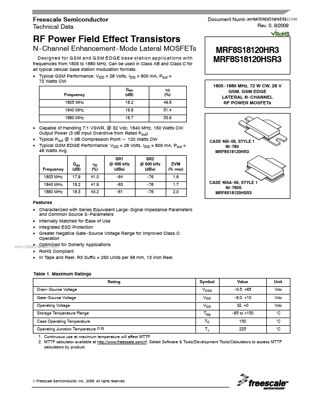
Mount Type: Surface Mount
Pins: 3
Max Frequency: 1.88 GHz
Max Operating Temp: 225 °C
Key Features
- Characterized with Series Equivalent Large
- Signal Impedance Parameters and Common Source S
- Internally Matched for Ease of Use
- Integrated ESD Protection
- Greater Negative Gate