7MBR75SB060
7MBR75SB060 is IGBT manufactured by Fuji Electric.
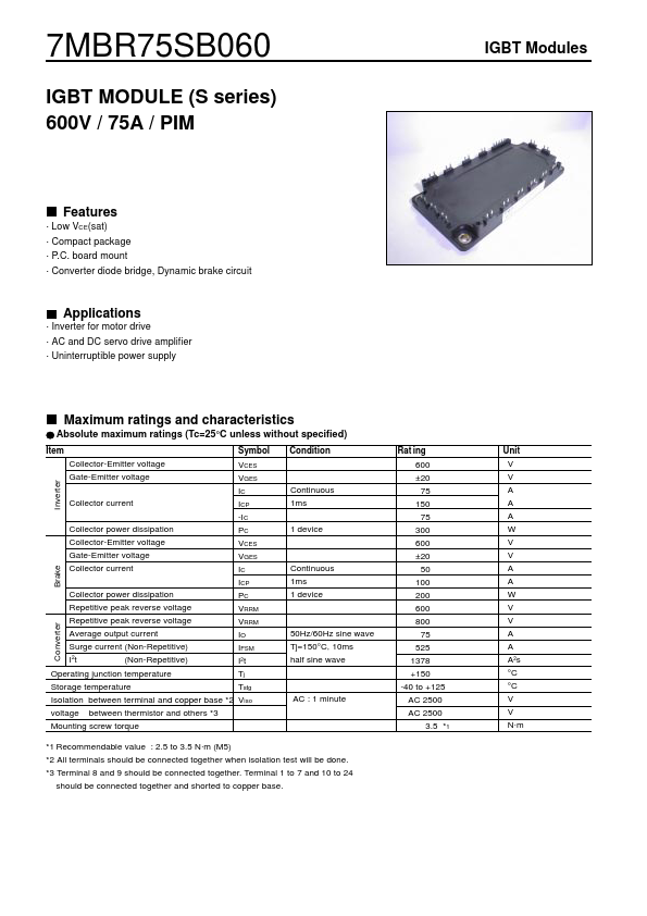
Features
- Low VCE(sat)
- pact package
- P.C. board mount
- Converter diode bridge, Dynamic brake circuit
Applications
- Inverter for motor drive
- AC and DC servo drive amplifier
- Uninterruptible power supply
Maximum ratings and characteristics
Absolute maximum ratings (Tc=25°C unless without specified)
Item Collector-Emitter voltage Gate-Emitter voltage Symbol Condition Rat ing 600 ±20 75 150 75 300 600 ±20 50 100 200 600 800 75 525 1378 +150 -40 to +125 AC 2500 AC 2500 3.5
- 1 VCES VGES IC Collector current ICP -IC Collector power dissipation PC Collector-Emitter voltage VCES Gate-Emitter voltage VGES Collector current IC ICP Collector power dissipation PC Repetitive peak reverse voltage VRRM Repetitive peak reverse voltage VRRM Average output current IO Surge current (Non-Repetitive) IFSM I 2t (Non-Repetitive) I2 t Operating junction temperature Tj Storage temperature Tstg Isolation between terminal and copper base
- 2 Viso voltage between thermistor and others
- 3 Mounting screw torque Inverter Brake Converter Unit V V A A A W V V A A W V V A A A 2s °C °C V V N- m
Continuous 1ms 1 device
Continuous 1ms 1 device
50Hz/60Hz sine wave Tj=150°C, 10ms half sine wave
AC : 1 minute
- 1 Remendable value : 2.5 to 3.5 N- m (M5)
- 2 All terminals should be connected together when isolation test will be done.
- 3 Terminal 8 and 9 should be connected together. Terminal 1 to 7 and 10 to 24 should be connected together and shorted to copper base.
IGBT Modules
Electrical characteristics (Tj=25°C unless otherwise specified)
Item Zero gate voltage collector current Gate-Emitter leakage current Gate-Emitter threshold voltage Collector-Emitter saturation voltage Input capacitance Turn-on time Symbol ICES IGES VGE(th) VCE(sat) Cies ton tr tr(i) toff tf VF trr ICES IGES VCE(sat) ton tr toff tf IRRM VFM IRRM R B Condition VCE=600V, VGE=0V VCE=0V, VGE=±20V VCE=20V, IC=75m A VGE=15V, Ic=75A chip terminal VGE=0V, VCE=10V, f=1MHz VCC=300V IC=75A VGE=±15V RG=33Ω IF=75A chip terminal...