Fuji Electric 7MBP75RTB-060
IGBT
| Part No. | 7MBP75RTB-060 |
|---|---|
| Datasheet | 7MBP75RTB-060 Download |
| Manufacturer |  Fuji Electric |
| Description | IGBT |
| Buy | Stock & Price |
DESCRIPTION
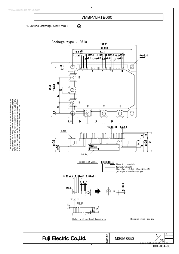
Positive input supply voltage. Output (U). Output (V). Output (W). Negative input supply voltage. Collector terminal of Brake IGBT. Control circuit № ① ② ③ Symbol GNDU High side ground (U). VinU VccU Logic input for IGBT gate drive (U). High side supply voltage (U).DESCRIPTION
④ ⑤ ⑥ GNDV High side ground (V). VinV VccV Logic input for IGBT gate drive (V). High side supply voltage (V). ⑦ ⑧ ⑨ GNDW High side ground (W). VinW VccW Logic input for IGBT gate drive (W). High side supply voltage (W). ⑩ ⑪ ⑫ ⑬ ⑭ ⑮ ⑯ GND Vcc Low side ground. Low side supply voltage. VinDB Logic input for Brake IGBT gate drive. VinX VinY VinZ ALM Logic input for IGBT gate drive (X). Logic input for IGBT gate drive (Y). Logic input for IGBT gate drive (Z). Low side alarm signal output. MS6M 0653 4 23 a H04-004-03 3. Block Diagram VccU VinU GNDU VccV cV VinV GNDV VccW VinW 3 P Pre- Driver VZ 2 1 6 U 5 VZ 4 9 Pre- Driver V 8 VZ Pre- Driver GNDW 7 Vcc VinX GND 11 W 13 Pre- Driver VZ 10 VinY 14 Pre- Driver VZ VinZ 15 Pre- Driver VZ B VinDB Pre- Driver VZ 12 N RALM ALM 16 Over heat ing prot ect ion circuit 1.