Fuji Electric MP2A5077
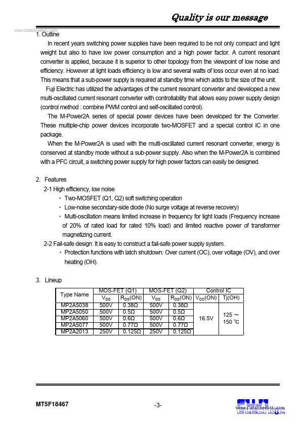
This means that a sub-power supply is required at standby time which adds to the size of the unit. The M-Power2A series of special power devices have been developed for the Converter.| Part No. | MP2A5077 |
|---|---|
| Datasheet | MP2A5077 Download |
| Manufacturer |  Fuji Electric |
| Description | M-Power 2A |
| Buy | Stock & Price |

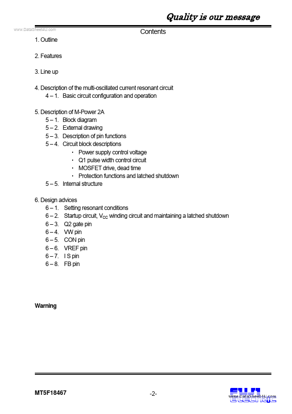
FEATURES
3. Line up 4.DESCRIPTION
of the multi-oscillated current resonant circuit 4 – 1. Basic circuit configuration and operation 5.DESCRIPTION
of M-Power 2A 5 – 1. Block diagram 5 – 2. External drawing 5 – 3.DESCRIPTION
of pin functions 5 – 4. Circuit block descriptions● Power supply control voltage
● Q1 pulse width control circuit
● MOSFET drive, dead time
● Protection functions and latched shutdown 5 – 5. Internal structure 6. Design advices 6 – 1. Setting resonant conditions 6 – 2. Startup circuit, VCC winding circuit and maintaining a latched shutdown 6 – 3. Q2 gate pin 6 – 4. VW pin 6 – 5. CON pin 6 – 6. VREF pin 6 – 7. I S pin 6 – 8. FB pin Warning MT5F18467 -2- Quality is our message 1. Outline In recent years switching power supplies have been required to be not only compact and light weight but also to have low power consumption and a high power factor. A current resonant converter is applied, because it is superior to other topology from the viewpoint of low noise and efficiency.