7MBP75RTB060
7MBP75RTB060 is IGBT manufactured by Fuji Electric.
Features
- Temperature protection provided by directly detecting the junction temperature of the IGBTs
- Low power loss and soft switching
- High performance and high reliability IGBT with overheating protection
- Higher reliability because of a big decrease in number of parts in built-in control circuit
..
600V / 75A 7 in one-package
Maximum ratings and characteristics
Absolute maximum ratings(at Tc=25°C unless otherwise specified)
Item Symbol Min. Bus voltage (between terminal P and N) Collector-Emitter voltage Collector current
Inverter
Rating Max. 450 500 400 600 75 150 75 198 50 100 50 198 20 Vcc+0.5 3 Vcc 20 150 100 125 AC2.5 3.5
- 9 3.5
- 9
Unit V V V V A A A W A A A W V V m A V m A °C °C °C k V N- m N- m
VDC DC VDC(surge) Surge Shortoperating V SC VCES
- 1 DC IC 1ms ICP Duty=75.0% -IC
- 2 Collector power dissipation One transistor PC
- 3 Collector current DC IC 1ms ICP Forward Current of Diode IF Collector power dissipation One transistor PC
- 3 Input voltage of power supply for Pre-Driver VCC
- 4 Input signal voltage Vin
- 5 Input signal current Iin Alarm signal voltage VALM
- 6 Alarm signal current IALM
- 7 Junction temperature Tj Operating case temperature Top Storage temperature Tstg Isolating voltage (Case-Terminal) Viso
- 8 Screw torque Mounting (M5) Terminal (M5)
Brake
Note
0 0 200 0 -0.5 -0.5 -0.5 -20 -40
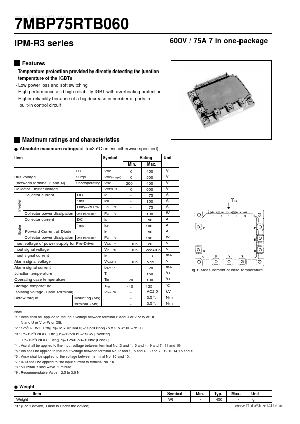
- Fig.1 Measurement of case temperature
- 1 : Vces shall be applied to the input voltage between terminal P and U or V or W or DB, N and U or V or W or DB.
- 2 : 125°C/FWD Rth(j-c)/(Ic x VF MAX)=125/0.855/(75 x 2.6)x100=75.0%
- 3 : Pc=125°C/IGBT Rth(j-c)=125/0.63=198W [Inverter] Pc=125°C/IGBT Rth(j-c)=125/0.63=198W [Break]
- 4 : Vcc shall be applied to the input voltage between terminal No. 3 and 1, 6 and 4, 9 and 7, 11 and 10.
- 5 : Vin shall be applied to the input voltage between terminal No. 2 and 1, 5 and 4, 8 and 7, 12,13,14,15 and 10.
- 6 : VALM shall be spplied to the voltage between terminal No. 16 and 10.
- 7 : IALM shall be applied to the input...