FMW20N60S1HF
FMW20N60S1HF is N-CHANNEL SILICON POWER MOSFET manufactured by Fuji Electric.
Features
Low on-state resistance Low switching loss easy to use (more controllabe switching d V/dt by Rg)
FUJI POWER MOSFET
N-Channel enhancement mode power MOSFET
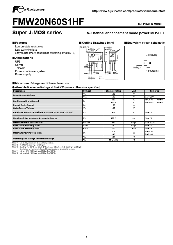
Outline Drawings [mm]
TO-247-P2
Equivalent circuit schematic
Applications
UPS Server Tele Power conditioner system Power supply
Gate(G)
Drain(D)
Source(S)
CONNECTION ① GATE ② DRAIN ③ SOURCE DIMENSIONS ARE IN MILLIMETERS.
Maximum Ratings and Characteristics
Absolute Maximum Ratings at TC =25°C (unless otherwise specified)
Description
Drain-Source Voltage Continuous Drain Current Pulsed Drain Current Gate-Source Voltage Repetitive and Non-Repetitive Maximum Avalanche Current Non-Repetitive Maximum Avalanche Energy Maximum Drain-Source d V/dt Peak Diode Recovery d V/dt Peak Diode Recovery -di/dt Maximum Power Dissipation Operating and Storage Temperature range
Note
- 1 : Limited by maximum channel temperature. Note
- 2 : Tch ≤150°C, See Fig.1 and Fig.2 Note
- 3 : Starting Tch =25°C, IAS=2A, L=216m H, VDD =60V, RG =50Ω, See Fig.1 and Fig.2 E AS limited by maximum channel temperature and avalanche current. Note
- 4 : I F ≤-I D, -di/dt=100A/μs, VDD ≤400V, Tch ≤150°C. Note
- 5 : I F ≤-I D, d V/dt=15k V/μs, VDD ≤400V, Tch ≤150°C.
Symbol VDS VDSX ID IDP VGS IAR EAS d VDS /dt d V/dt -di/dt PD Tch Tstg
Characteristics 600 600 ±20 ±12.6 ±60 ±30 6.6 472.2 50 15 100 2.5 140 150 -55 to +150
Unit V V A A A V A m J k V/μs k V/μs A/μs W °C °C
Remarks VGS=-30V Tc=25°C Tc=100°C
Note- 1 Note- 1
Note
- 2 Note
- 3 VDS ≤ 600V Note
- 4 Note
- 5 Ta =25°C Tc=25°C
Datasheet pdf
- http://..net/
.Data Sheet.co.kr
Electrical Characteristics at TC =25°C (unless otherwise specified) Static Ratings
Description
Drain-Source Breakdown Voltage Gate Threshold Voltage Symbol BVDSS VGS(th) Conditions ID =250μA VGS=0V ID =250μA VDS=VGS VDS=600V VGS=0V VDS=480V VGS=0V VGS= ± 30V VDS=0V ID =10A VGS=10V f=1MHz, open drain ID =10A VDS=25V VDS=10V VGS=0V f=1MHz VGS=0V VDS=0…480V VGS=0V VDS=0…480V ID=constant VDD =400V, VGS=10V ID =10A, RG...