SR1A
SR1A is SURFACE MOUNT FAST SWITCHING RECTIFIER manufactured by Good-Ark Semiconductor.
- Part of the SR1A_GOOD comparator family.
- Part of the SR1A_GOOD comparator family.
Features
For surface mounted applications Low profile package Built-in strain relief Easy pick and place Fast recovery times for high efficiency Plastic package has Underwriters Laboratory Flammability Classification 94V-0 High temperature soldering: 260 /10 seconds at terminals
Mechanical Data
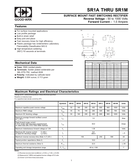
Case: SMA molded plastic Terminals: Solder plated solderable per MIL-STD-750, method 2026 Polarity: Indicated by cathode band Weight: 0.004 ounce, 0.113 gram
D IM E N S IO N S D IM A B C D E F G H J K L M N P in c h e s M in . 0 .2 1 6 0 .1 7 6 0 .0 9 4 0 .1 7 0 0 .0 3 9 0 .0 8 0 0 .0 6 8 0 .1 1 2 0 .0 5 7 0 .0 1 6 0 .1 0 9 0 .1 0 5 0 .0 7 8 M a x . 0 .2 2 6 0 .1 8 2 0 .1 0 0 0 .1 7 6 0 .0 5 5 0 .0 8 1 0 .0 8 3 0 .1 1 8 0 .0 1 8 0 .1 1 5 0 .1 0 7 0 .0 8 1 M in . 5 .4 8 4 .4 8 2 .4 0 4 .3 3 1 .0 0 2 .0 3 1 .7 2 2 .8 5 1 .4 4 0 .4 0 2 .7 7 2 .6 7 2 .0 0 m m M a x . 5 .7 4 4 .6 3 2 .5 5 4 .4 8 1 .4 0 2 .0 7 2 .1 0 3 .0 0 0 .4 5 2 .9 3 2 .7 3 2 .0 5 N o te
Maximum Ratings and Electrical Characteristics
Ratings at 25 ambient temperature unless otherwise specified. Resistive or inductive load. For capacitive load, derate current by 20%.
Symbols
SR1B
SR1D
SR1G
SR1J
SR1K
SR1M
Units
Maximum repetitive peak reverse voltage Maximum RMS voltage Maximum DC blocking voltage Maximum average forward rectified current at TL=90 Peak forward surge current 8.3m S single half sine-wave superimposed on rated load (MIL-STD-750D 4066 method) Maximum instantaneous forward voltage at 1.0A Maximum DC reverse current at rated DC blocking voltage TA=25 TA=125
VRRM VRMS VDC I(AV) IFSM VF IR Trr CJ R
50 35 50
100 70 100
200 140 200
400 280 400 1.0 30.0 1.30 5.0 300.0
600 420 600
800 560 800
1000 700 1000
Volts Volts Volts Amp Amps Volts A
Maximum reverse recovery time (Note 1) TJ=25 Typical junction capacitance (Note 2) Maximum thermal resistance (Note 3) Operating and storage temperature range
Notes: (1) Reverse recovery test conditions: IF=0.5A, IR=1.0A, Irr=0.25A (2)...