SRA8 Overview
Key Specifications
Max Operating Temp: 125 °C
Min Operating Temp: -65 °C
Key Features
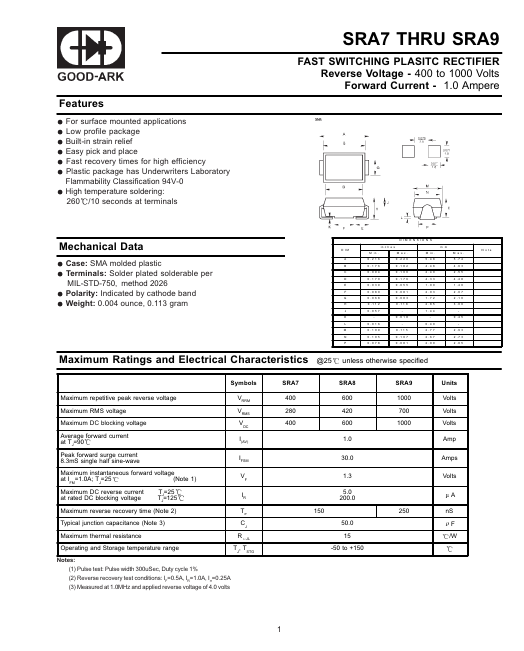
- 400 to 1000 Volts Forward Current
| Part | SRA8 |
|---|---|
| Description | FAST SWITCHING PLASITC RECTIFIER |
| Manufacturer | Good-Ark Semiconductor |
| Size | 202.25 KB |
Max Operating Temp: 125 °C
Min Operating Temp: -65 °C
| Seller | Inventory | Price Breaks | Buy |
|---|---|---|---|
| DigiKey | 0 | 1000+ : 0.33922 USD | View Offer |
| Avnet | 0 | 1000+ : 0.3234 USD 2000+ : 0.29738 USD 4000+ : 0.29585 USD 8000+ : 0.29433 USD |
View Offer |
| Part Number | Manufacturer | Description |
|---|---|---|
| SRA820 | Taiwan Semiconductor | Schottky Barrier Rectifiers |
| SRA8200 | Taiwan Semiconductor | Schottky Barrier Rectifiers |
| SRA840 | Taiwan Semiconductor | Schottky Barrier Rectifiers |
| SRA850 | Taiwan Semiconductor | Schottky Barrier Rectifiers |
| SRA890 | Taiwan Semiconductor | Schottky Barrier Rectifiers |