Gamma GM3842A
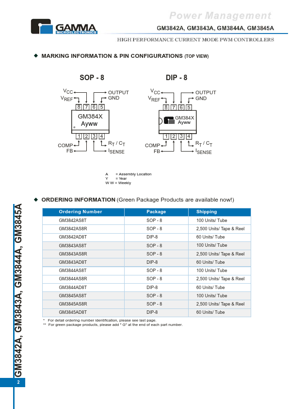
The GM384XA Have Start-up Current 0.17mA SIMPLIFIED BLOCK DIAGRAM VCC 7 Vref 8 R R VREF Undervoltage LOCKOUT OSCILLATOR Error Amplifier + Latching PWM 5 Power Ground 3 Current Sense Input 5 GND 5.0V REFERENCE VCC Undervoltage LOCKOUT 7 VC RT/ CT 4 6 Output Voltage Feedback Input 2 Output Compensation 1 GM3842A, GM3843A, GM3844A, GM3845A 1 GM 431 V1.0 MARKING INFORMATION & PIN CONFIGURATIONS (TOP VIEW) SOP - 8 VCC VREF 8 7 6 5 DIP - 8 OUTPUT GND VCC VREF 8 7 6 5 GM384X Ayww OUTPUT GND GM384X Ayww 1 2 3 4 1 2 3 4 COMP FB RT / C T ISENSE COMP FB RT / C T ISENSE A = Assembly Location Y = Year W W... This is the inverting input of the Error Amplifier.| Part No. | GM3842A |
|---|---|
| Datasheet | GM3842A Download |
| Manufacturer |  Gamma |
| Description | HIGH PERFORMANCE CURRENT MODE PWM CONTROLLERS |
| Buy | Stock & Price |