Hitachi HD74AC393
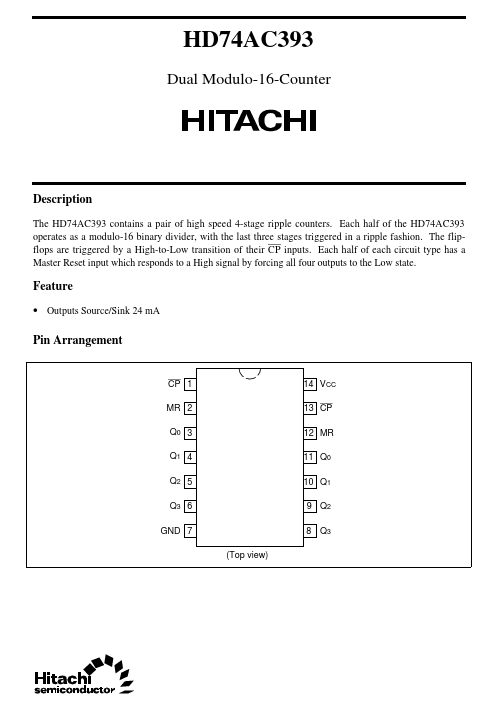
The HD74AC393 contains a pair of high speed 4-stage ripple counters. Each half of the HD74AC393 operates as a modulo-16 binary divider, with the last three stages triggered in a ripple fashion. The flipflops are triggered by a High-to-Low transition of their CP inputs.| Part No. | HD74AC393 |
|---|---|
| Datasheet | HD74AC393 Download |
| Manufacturer |  Hitachi |
| Description | Dual Modulo-16-Counter |
| Buy | Stock & Price |
DESCRIPTION
Each half of each circuit type has a Master Reset input which responds to a High signal by forcing all four outputs to the Low state. Feature● Outputs Source/Sink 24 mA Pin Arrangement CP 1 MR 2 Q0 3 Q1 4 Q2 5 Q3 6 GND 7 (Top view) 14 VCC 13 CP 12 MR 11 Q0 10 Q1 9 Q2 8 Q3 HD74AC393 Logic Symbol (each half) 1, 13 CP MR Q0 Q1 Q2 Q3 2, 12 3, 11 4, 10 5, 9 6, 8 Vcc=Pin14 GND=Pin7 Pin Names CP MR Q0 – Q3 Clock Pulse Input (Active Falling Edge) Asynchronous Master Reset Input (Active High) Flip-flop Outputs Functional
DESCRIPTION
Each half of the HD74AC393 operates in the modulo-16 binary sequence, as indicated in the + 16 Truth Table. The first flip-flop is triggered by High-to-Low transitions of the CP input signal. Each of the other flip-flops is triggered by a High-to-Low transition of the Q output of the preceding flip-flop. Thus state changes of the Q outputs do not occur simultaneously. This means that logic signals derived from combinations of these outputs will be subject to decoding spikes and, therefore, should not be used as clocks for other counters, registers or flip-flops.
