Hitachi HD74AC539
The HD74AC539 contains two inpedendent decoders. Each accepts two Address (A 0, A1) input signals and decodes them to select one of four mutually exclusive outputs.| Part No. | HD74AC539 |
|---|---|
| Datasheet | HD74AC539 Download |
| Manufacturer |  Hitachi |
| Description | Dual 1-of-4 Decoder with 3-State Output |
| Buy | Stock & Price |
DESCRIPTION
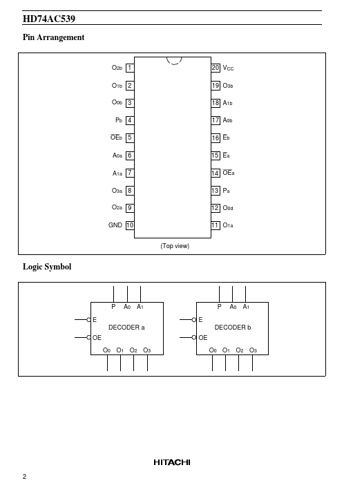
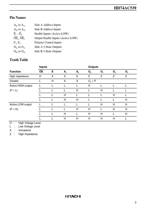
The HD74AC539 contains two inpedendent decoders. A polarity control input (P) determines whether the outputs are active HIGH (P = L) or active LOW (P = H). An active LOW input Enable (E) is available for data demultiplexing; data is routed to the selected output in non-inverted form in the active LOW mode or in inverted form in the active HIGH mode. A HIGH signal on the active LOW Output Enable ( OE) input forces the 3-state outputs to the high impedance state. Feature● Outputs Source/Sink 24 mA HD74AC539 Pin Arrangement O2b 1 O1b 2 O0b 3 Pb 4 OEb 5 A0a 6 A1a 7 O3a 8 O2a 9 GND 10 (Top view) 20 VCC 19 O3b 18 A1b 17 A0b 16 Eb 15 Ea 14 OEa 13 Pa 12 O0d 11 O1a Logic Symbol P E A0 A1 E P A0 A1 DECODER a OE O0 O1 O2 O3 OE DECODER b O0 O1 O2 O3 2 HD74AC539 Pin Names A0a to A1a A0b to A1b Ea – Eb OEa , OEb P a, P b O0a to O3a O0b to O3b Side A Address Inputs Side B Address Inputs Enable Inputs (Active LOW) Output Enable Inputs (Active LOW) Polarity Control Inputs Side A 3-State Ou...