DESCRIPTION
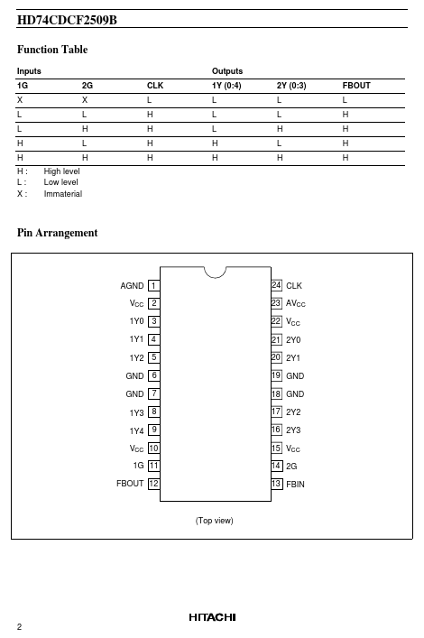
The HD74CDCF2509B operates at 3.3 V VCC and is designed to drive up to five clock loads per output. One bank of five outputs and one bank of four outputs provide nine low-skew, low-jitter copies of the input clock. Output signal duty cycles are adjusted to 50 percent independent of the duty cycle at the input clock. Each bank of outputs can be enabled or disabled separately via the control (1G and 2G) inputs. When the G inputs are high, the outputs switch in phase and frequency with CLK; when the G inputs are low, the outputs are disabled to the logic-low state. Unlike many products containing PLLs, the HD74CDCF2509B does not require external RC networks. The loop filter for the PLL is included on-chip, minimizing component count, board space, and cost. Because it is based on PLL circuitry, HD74CDCF2509B requires a stabilization time to achieve phase lock of the feedback signal to the reference signal. This stabilization time is required, following power up and application of a fixed-frequency, fixed-phase signal at CLK, as well as following any changes to the PLL reference or feedback signals. Hitachi