Hitachi HD74HC157
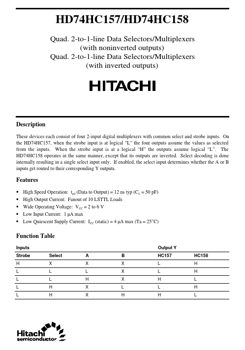
the HD74HC157, when the strobe input is at logical “L” the four outputs assume the values as selected from the inputs. When the strobe input is at a logical “H” the outputs assume logical “L”. The HD74HC158 operates in the same manner, except that its outputs are inverted.| Part No. | HD74HC157 |
|---|---|
| Datasheet | HD74HC157 Download |
| Manufacturer |  Hitachi |
| Description | These devices each consist of four 2-input digital multiplexers with common select and strobe inputs |
| Buy | Stock & Price |
DESCRIPTION
These devices each consist of four 2-input digital multiplexers with common select and strobe inputs. On Select decoding is done internally resulting in a single select input only. If enabled, the select input determines whether the A or B inputs get routed to their corresponding Y outputs.FEATURES
●●
●
●
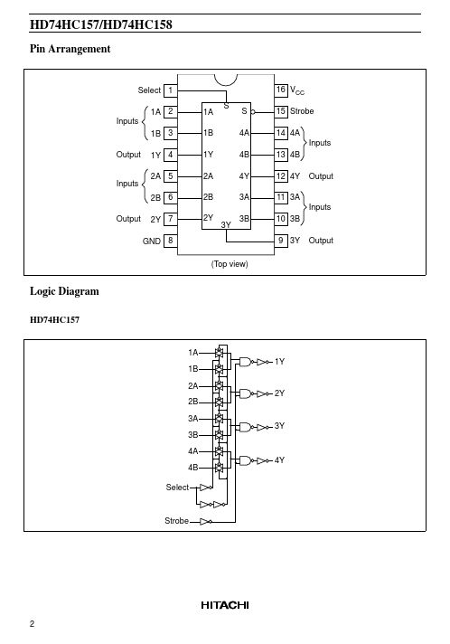
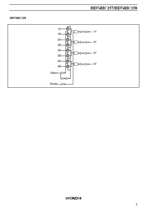
● High Speed Operation: tpd (Data to Output) = 12 ns typ (CL = 50 pF) High Output Current: Fanout of 10 LSTTL Loads Wide Operating Voltage: VCC = 2 to 6 V Low Input Current: 1 µA max Low Quiescent Supply Current: ICC (static) = 4 µA max (Ta = 25°C) Function Table Inputs Strobe H L L L L Select X L L H H A X L H X X B X X X L H Output Y HC157 L L H L H HC158 H H L H L HD74HC157/HD74HC158 Pin Arrangement Select 1 1A 2 Inputs 1B 3 Output 1Y 4 2A 5 2B 6 Output 2Y 7 GND 8 (Top view) 1B 1Y 2A 2B 2Y 4A 4B 4Y 3A 3Y 3B 1A S S 16 VCC 15 Strobe 14 4A Inputs 13 4B 12 4Y 11 3A Inputs 10 3B 9 3Y Output Output Inputs Logic Diagram HD74HC157 1A 1B 2A 2B 3A 3B 4A 4B Select 4Y 3Y 1Y 2Y St...