Hitachi HD74HC386
The circuits are designed to prevent false clocking by transitions at the G input.| Part No. | HD74HC386 |
|---|---|
| Datasheet | HD74HC386 Download |
| Manufacturer |  Hitachi |
| Description | Quad. 2-input Exclusive-OR Gates |
| Buy | Stock & Price |
DESCRIPTION
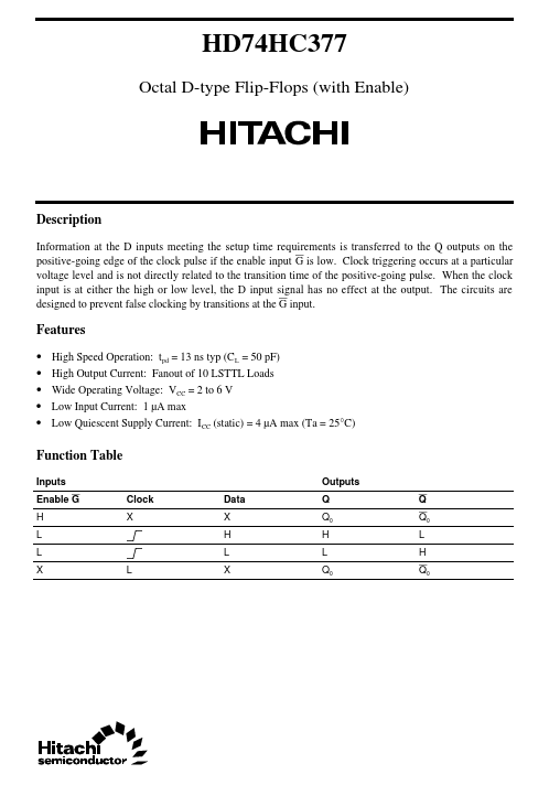
Information at the D inputs meeting the setup time requirements is transferred to the Q outputs on the positive-going edge of the clock pulse if the enable input G is low. Clock triggering occurs at a particular voltage level and is not directly related to the transition time of the positive-going pulse. When the clock input is at either the high or low level, the D input signal has no effect at the output.FEATURES
●●
●
●
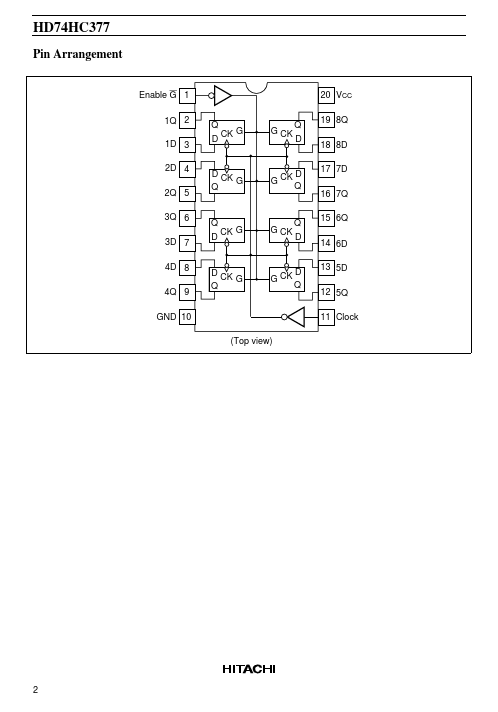
● High Speed Operation: tpd = 13 ns typ (CL = 50 pF) High Output Current: Fanout of 10 LSTTL Loads Wide Operating Voltage: VCC = 2 to 6 V Low Input Current: 1 µA max Low Quiescent Supply Current: ICC (static) = 4 µA max (Ta = 25°C) Function Table Inputs Enable G H L L X L Clock X Data X H L X Outputs Q Q0 H L Q0 Q Q0 L H Q0 HD74HC377 Pin Arrangement Enable G 1 1Q 2 1D 3 2D 4 2Q 5 3Q 6 3D 7 4D 8 4Q 9 GND 10 (Top view) Q D Q D 20 VCC 19 8Q 18 8D 17 7D 16 7Q 15 6Q 14 6D 13 5D 12 5Q 11 Clock CK G G CK D CK G Q G CK D Q Q D CK G G CK Q D D CK G Q G CK D Q 2 H...