Hitachi HD74HCT534
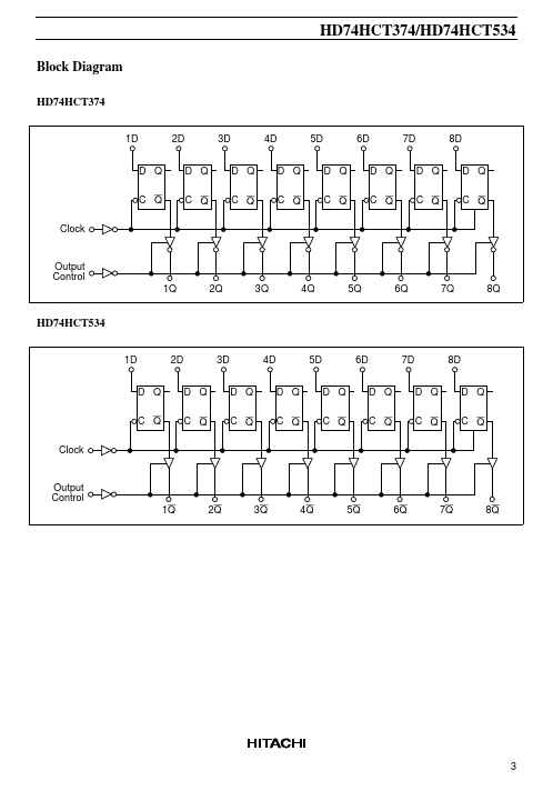
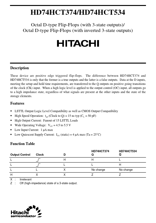
HD74HCT534 is only that the former is a true outputs and the latter is a false outputs. When a high logic level is applied to the output control (OC) input, all outputs go to a high impedance state, regardless of what signals are present at the other inputs and the state of the storage elements.| Part No. | HD74HCT534 |
|---|---|
| Datasheet | HD74HCT534 Download |
| Manufacturer |  Hitachi |
| Description | Octal D-type Flip-Flops(with inverted 3-state outputs) |
| Buy | Stock & Price |
DESCRIPTION
These device are positive edge triggered flip-flops. The difference between HD74HCT374 and Data at the D inputs, meeting the setup and hold time requirements, are transferred to the Q outputs on positive going transitions of the clock (CK) input.FEATURES
●●
●
●
●
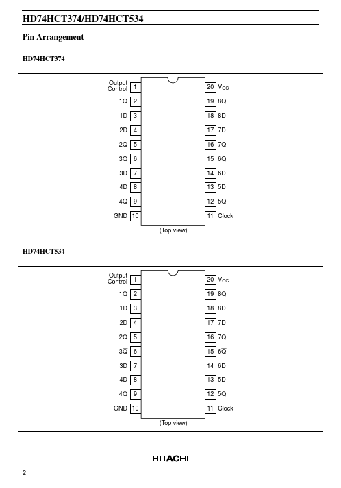
● LSTTL Output Logic Level Compatibility as well as CMOS Output Compatibility High Speed Operation: tpd (Clock to Q) = 15 ns typ (CL = 50 pF) High Output Current: Fanout of 15 LSTTL Loads Wide Operating Voltage: VCC = 4.5 to 5.5 V Low Input Current: 1 µA max Low Quiescent Supply Current: ICC (static) = 4 µA max (Ta = 25°C) Function Table Output Control L L L H X : Z : L X Clock D H L X X HD74HCT374 Q H L No change Z HD74HCT534 Q L H No change Z Irrelevant Off (high-impedance) state of a 3-state output. HD74HCT374/HD74HCT534 Pin Arrangement HD74HCT374 Output Control 1 1Q 1D 2D 2Q 3Q 3D 4D 4Q 2 3 4 5 6 7 8 9 20 VCC 19 8Q 18 8D 17 7D 16 7Q 15 6Q 14 6D 13 5D 12 5Q 11 Clock (Top view) GND 10 HD74HCT534 Output Control...