HD74LV157A
HD74LV157A is Quad. 2-to-1 line Data Selectors / Multiplexers(Noninverted Outputs) manufactured by Hitachi Semiconductor.
Description
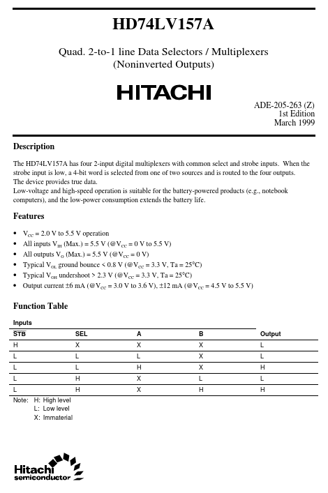
The HD74LV157A has four 2-input digital multiplexers with mon select and strobe inputs. When the strobe input is low, a 4-bit word is selected from one of two sources and is routed to the four outputs. The device provides true data. Low-voltage and high-speed operation is suitable for the battery-powered products (e.g., notebook puters), and the low-power consumption extends the battery life.
Features
- -
- -
- - VCC = 2.0 V to 5.5 V operation All inputs VIH (Max.) = 5.5 V (@VCC = 0 V to 5.5 V) All outputs VO (Max.) = 5.5 V (@VCC = 0 V) Typical VOL ground bounce < 0.8 V (@VCC = 3.3 V, Ta = 25°C) Typical VOH undershoot > 2.3 V (@VCC = 3.3 V, Ta = 25°C) Output current ±6 m A (@VCC = 3.0 V to 3.6 V), ±12 m A (@VCC = 4.5 V to 5.5 V)
Function Table
Inputs STB H L L L L Note: H: High level L: Low level X: Immaterial SEL X L L H H A X L H X X B X X X L H Output L L H L H
Pin Arrangement
SEL 1 1A 2 1B 3 1Y 4 2A 5 2B 6 2Y 7 GND 8 A S G B Y A B A B Y A
16 VCC 15 STB 14 4A 13 4B 12 4Y 11 3A 10 3B 9 3Y
(Top view)
Absolute Maximum Ratings
Item Supply voltage range Input voltage range-
1 1, 2
Symbol VCC VI VO
Ratings
- 0.5 to 7.0
- 0.5 to 7.0
- 0.5 to VCC + 0.5
- 0.5 to 7.0
Unit V V V
Conditions
Output voltage range-
Output: H or L VCC: OFF
Input clamp current Output clamp current Continuous output current Continuous current through VCC or GND Maximum power dissipation at Ta = 25°C (in still air)- 3
I IK I OK IO I CC or IGND PT
- 20 ±50 ±25 ±50 785 500 m A m A m A m A m W
VI < 0 VO < 0 or VO > VCC VO = 0 to VCC
SOP TSSOP
Storage temperature
Tstg
- 65 to 150
°C
Notes: The absolute maximum ratings are values which must not individually be exceeded, and furthermore, no two of which may be realized at the same time. 1. The input and output voltage ratings may be exceeded if the input and output clamp-current ratings are observed. 2. This value is limited to 5.5 V maximum. 3. The maximum package power dissipation was calculated...