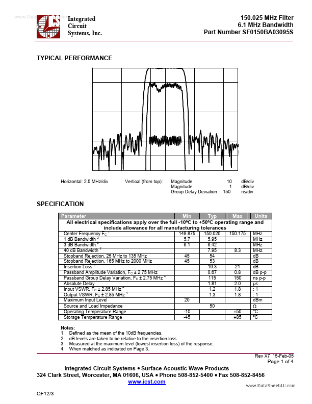
DESCRIPTION
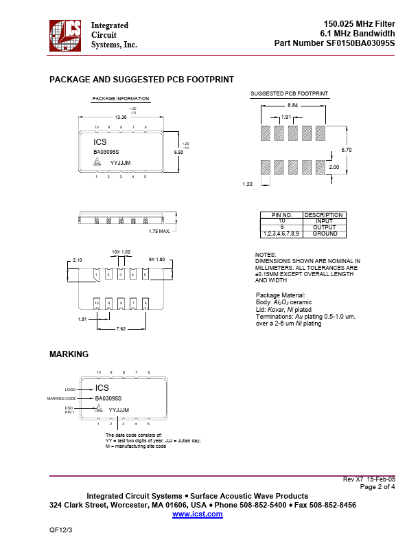
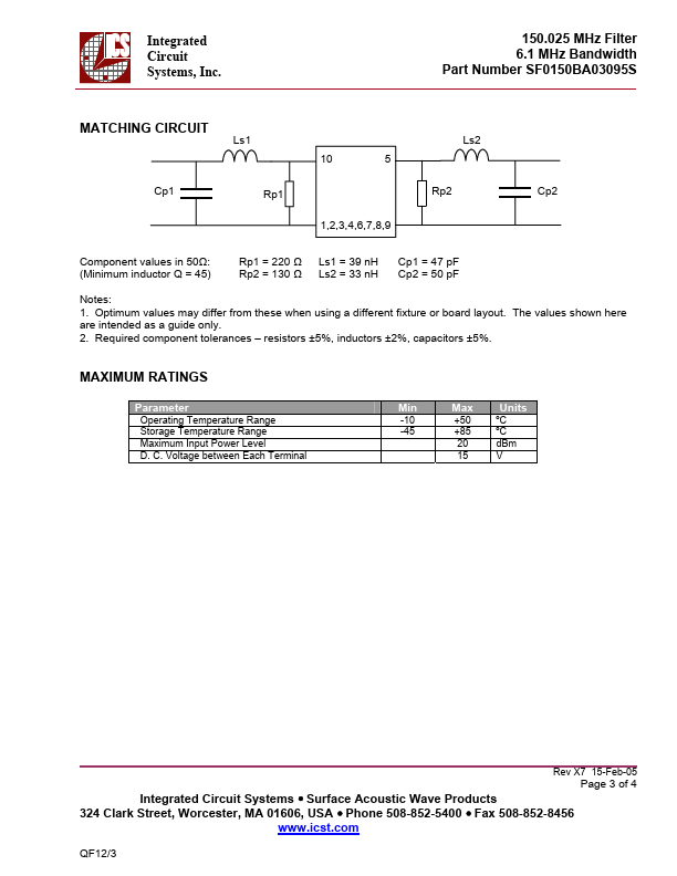
INPUT OUTPUT GROUND 10X 1.02 2.10 1 2 3 4 5 9X 1.80 NOTES: DIMENSIONS SHOWN ARE NOMINAL IN MILLIMETERS. ALL TOLERANCES ARE ±0.15MM EXCEPT OVERALL LENGTH AND WIDTH 10 9 8 7 6 1.91 7.62 Package Material: Body: Al2O3 ceramic Lid: Kovar, Ni plated Terminations: Au plating 0.5-1.0 um, over a 2-6 um Ni plating MARKING 10 9 8 7 6 LOGO MARKING CODE ESD PIN 1 ICS BA03095S YYWWM YYJJJM 1 2 3 4 5 THE DATE CODE CONSISTS OF: 150.025 MHz Filter 6.1 MHz Bandwidth Part Number SF0150BA03095S MATCHING CIRCUIT Ls1 10 5 Rp2 1,2,3,4,6,7,8,9 Ls2 Cp1 Rp1 Cp2 Component values in 50Ω: (Minimum inductor Q = 45) Rp1 = 220 Ω Rp2 = 130 Ω Ls1 = 39 nH Ls2 = 33 nH Cp1 = 47 pF Cp2 = 50 pF Notes: 1. Optimum values may differ from these when using a different fixture or board layout. 2. Required component tolerances – resistors ±5%, inductors ±2%, capacitors ±5%. MAXIMUM RATINGS
Parameter Operating Temperature Range Storage Temperature Range Maximum Input Power Level D. C. Voltage between Each Terminal Min -... ICS