International Rectifier IRF100B202
Power MOSFET
| Part No. | IRF100B202 |
|---|---|
| Datasheet | IRF100B202 Download |
| Manufacturer |  International Rectifier |
| Description | Power MOSFET |
| Buy | Stock & Price |
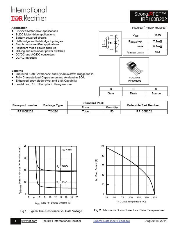
ELECTRICAL CHARACTERISTICS
@ TJ = 25°C (unless otherwise specified) Symbol gfs Qg Qgs Qgd Qsync td(on) tr td(off) tf Ciss Coss Crss Coss eff.(ER) Coss eff.(TR) Parameter Forward Transconductance Total Gate Charge Gate-to-Source Charge Gate-to-Drain Charge Total Gate Charge Sync. (Qg– Qgd) Turn-On Delay Time Rise Time Turn-Off Delay Time Fall Time Input Capacitance Output Capacitance Reverse Transfer Capacitance Effective Output Capacitance (Energy Related) Output Capacitance (Time Related) Min. 123 ––– ––– ––– ––– ––– ––– ––– ––– ––– ––– ––– ––– ––– Typ. ––– 77 20 23 54 11 56 55 58 4476 319 154 355 385 Max. Units Conditions ––– S VDS = 10V, ID =58A 116 ID = 58A ––– ––– nC VVDGSS = = 50V 10V ––– ––– VDD = 65V ––– ––– ns ID = 58A RG= 2.7 ––– VGS = 10V ––– VGS = 0V ––– VDS = 50V ––– pF ƒ = 1.0MHz, See Fig.5 ––– VGS = 0V, VDS = 0V to 80V ––– VGS = 0V, VDS = 0V to 80V Diode Characteristics Symbol IS ISM Para