International Rectifier IRF60DM206
N-Channel Power MOSFET
| Part No. | IRF60DM206 |
|---|---|
| Datasheet | IRF60DM206 Download |
| Manufacturer |  International Rectifier |
| Description | N-Channel Power MOSFET |
| Buy | Stock & Price |
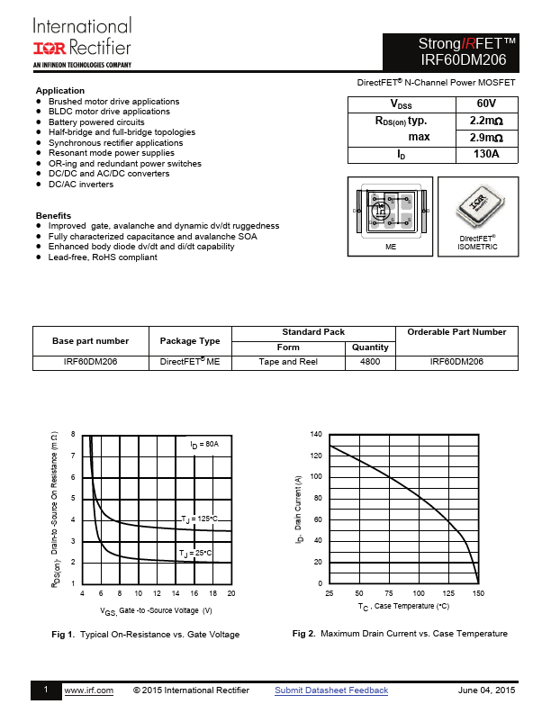
ABSOLUTE MAXIMUM RATINGS
Symbol Parameter ID @ TC = 25°C Continuous Drain Current, VGS @ 10V ID @ TC = 100°C IDM PD @TC = 25°C Continuous Drain Current, VGS @ 10V Pulsed Drain Current Maximum Power Dissipation Linear Derating Factor VGS TJ TSTG Gate-to-Source Voltage Operating Junction and Storage Temperature Range Avalanche Characteristics EAS (Thermally limited) Single Pulse Avalanche Energy EAS (Thermally limited) Single Pulse Avalanche Energy IAR Avalanche Current EAR Repetitive Avalanche Energy Thermal Resistance Symbol Parameter R●JA R●JA R●JA R●JC R●J-PCB Junction-to-Ambient Junction-to-Ambient Junction-to-Ambient Junction-to-Case Junction-to-PCB Mounted Max. 130 82 530 96 0.78 ± 20 -55 to + 150 Units A W W/°C V °C 81 154 See Fig 15, 15, 23a, 23b mJ A mJ Typ. ––– 12.5 20 ––– 0.75 Max. 45 ––– ––– 1.3 ––– Units °C/W Static @ TJ = 25°C (unless otherwise specified) Symbol Parameter V(BR)DSS Drain-to-Source Breakdown Voltage V(BR)DSS/TJ Breakdown Voltage Temp.