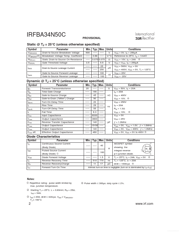
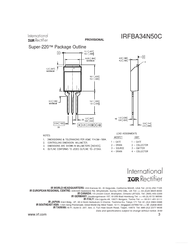
International Rectifier IRFBA34N50C
Power MOSFET
| Part No. | IRFBA34N50C |
|---|---|
| Datasheet | IRFBA34N50C Download |
| Manufacturer |  International Rectifier |
| Description | Power MOSFET |
| Buy | Stock & Price |
APPLICATIONS
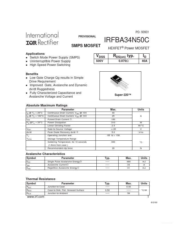
l Switch Mode Power Supply (SMPS) l UninterruptIble Power Supply l High Speed Power Switching Benefits l Low Gate Charge Qg results in Simple Drive Requirement l Improved Gate, Avalanche and Dynamic dv/dt Ruggedness l Fully Characterized Capacitance and Avalanche Voltage and CurrentABSOLUTE MAXIMUM RATINGS
Parameter ID @ TC = 25°C ID @ TC = 100°C IDM PD @TC = 25°C VGS dv/dt TJ TSTG Continuous Drain Current, VGS @ 10V Continuous Drain Current, VGS @ 10V Pulsed Drain Current Power Dissipation Linear Derating Factor Gate-to-Source Voltage Peak Diode Recovery dv/dt Operating Junction and Storage Temperature Range Soldering Temperature, for 10 seconds (1.6mm from case ) Recommended clip force VDSS 500V RDS(on) typ. 0.070Ω ID 40A Super-220™ Max. 40 25 160 310 2.5 ± 20 5.0 -55 to + 150 300 20 Units A W W/°C V V/ns °C N Avalanche Characteristics Symbol EAS IAR EAR Parameter Single Pulse Avalanche Energy Avalanche Current Repetitive Avalanche Energy Typ. ––– ––– ––– Max. 480 34 31 Units mJ A mJ Thermal Resistance Symbol RθJC RθCS RθJA Parameter Junction-to-Case Case-to-Sink, Flat, Greased Surface Junction-to-Ambient Typ.