Datasheet4U Logo Datasheet4U.com

IRFS3207 - Power MOSFET

Key Features

  • ion in Avalanche is allowed as long as neitherTjmax nor Iav (max) is exceeded. 3. Equation below based on circuit and waveforms shown in Figures 16a, 16b. 4. PD (ave) = Average power dissipation per single avalanche pulse. 5. BV = Rated breakdown voltage (1.3 factor accounts for voltage increase during avalanche). 6. Iav = Allowable avalanche current. 7. ∆T = Allowable rise in junction temperature, not to exceed Tjmax (assumed as 25°C in Figure 14, 15). tav = Average time in avalanche. D = Duty.

📥 Download Datasheet

Datasheet Details

Part number IRFS3207
Manufacturer IRF
File Size 373.35 KB
Description Power MOSFET
Datasheet download datasheet IRFS3207 Datasheet

Full PDF Text Transcription (Reference)

The following content is an automatically extracted verbatim text from the original manufacturer datasheet and is provided for reference purposes only.

View original datasheet text
Applications l High Efficiency Synchronous Rectification in SMPS l Uninterruptible Power Supply l High Speed Power Switching l Hard Switched and High Frequency Circuits Benefits l Worldwide Best RDS(on) in TO-220 l Improved Gate, Avalanche and Dynamic dV/dt Ruggedness l Fully Characterized Capacitance and Avalanche SOA l Enhanced body diode dV/dt and dI/dt Capability G PD - 96893C 
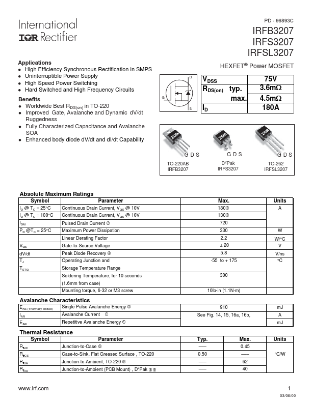
IRFB3207 IRFS3207 IRFSL3207 HEXFET® Power MOSFET D VDSS RDS(on) typ. max. S ID 3.765mV: 4.