International Rectifier IRFY440
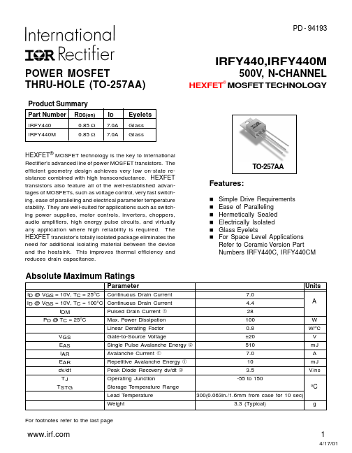
The efficient geometry design achieves very low on-state resistance combined with high transconductance. They are well-suited for applications such as switching power supplies, motor controls, inverters, choppers, audio amplifiers, high energy pulse circuits, and virtually any application where high reliability is required.
| Part No. |
IRFY440 |
| Datasheet |
IRFY440
Download
|
| Manufacturer |
 International Rectifier |
| Description |
POWER MOSFET |
| Buy |
Stock & Price
|
FEATURES
: n Simple Drive Requirements n Ease of Paralleling n Hermetically Sealed n Electrically Isolated n Glass Eyelets n For Space Level APPLICATIONS
Refer to Ceramic Version Part Numbers IRFY440C, IRFY440CM ABSOLUTE MAXIMUM RATINGS
Parameter ID @ VGS = 10V, TC = 25°C Continuous Drain Current ID @ VGS = 10V, TC = 100°C Continuous Drain Current IDM Pulsed Drain Current ➀ PD @ TC = 25°C Max. Power Dissipation Linear Derating Factor Units 7.0 4.4 A 28 100 W 0.8 W/°C VGS EAS IAR EAR dv/dt TJ TSTG Gate-to-Source Voltage ±20 V Single Pulse Avalanche Energy ➁ 510 mJ Avalanche Current ➀ 7.0 A Repetitive Avalanche Energy ➀ 10 mJ Peak Diode Recovery dv/dt ➂ Operating Junction Storage Temperature Range 3.5 -55 to 150 V/ns oC Lead Temperature Weight 300(0.063in./1.6mm from case for 10 sec) 3.3 (Typical) g For footnotes refer to the last page 1 4/17/01 IRFY440, IRFY440M ELECTRICAL CHARACTERISTICS
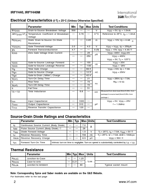
@ Tj = 25°C (Unless Otherwise Specified) Parameter BVDSS Drain-to-Source Breakdown Voltage ∆BVDSS/∆T...