DESCRIPTION
/ FEATURES
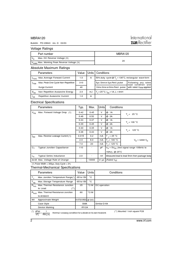
Units A V A V °C Typical applications are in disk drives, switching power supplies, converters, free-wheeling diodes, battery charging, and reverse battery protection. Small foot print, surface mountable Low forward voltage drop High frequency operation Guard ring for enhanced ruggedness and long term reliability MBRA120 1.0 20 310 0.34 - 65 to 150 Device Marking: IR12A CATHODE AN OD E 1.40 (.055) 1.60 (.062) 2.50 (.098) 2.90 (.114) 1 2 4.00 (.157) 4.60 (.181) .152 (.006) .305 (.012) 2.00 (.078) 2.44 (.096) 0.76 (.030) 1.52 (.060) .103 (.004) .203 (.008) 4.80 (.188) 5.28 (.208) 1 P O LA R I TY 2 PA R T N U M B ER 2.10 MAX. (.085 MAX. ) 1.47 MIN. (.058 MIN.) 1.27 MIN. (.050 MIN.) 5.53 (.218) SOLDERING PAD Outline SMA Similar to D-64 Dimensions in millimeters and (inches) For recommended footprint and soldering techniques refer to application note #AN-994 1 MBRA120 Bulletin PD-20643 rev. D 03/03 Voltage Ratings Part number VR Max. DC Reverse Voltage (V) 20 VRWM Max. Working Peak Reverse Voltage (V) MBRA120 ABSOLUTE MAXIMUM RATINGS
Parameters IF(AV) Max. International Rectifier