IXFC12N80P Datasheet Text
Advance Technical Information
PolarHVTM HiPerFET Power MOSFET ISOPLUS220TM
(Electrically Isolated Back Surface)
IXFC 12N80P
VDSS ID25
RDS(on) trr
= 800 V = 7 A ≤ 0.93 mΩ ≤ 250 ns
N-Channel Enhancement Mode Fast Intrinsic Diode Avalanche Rated
Symbol VDSS VDGR VGS VGSM ID25 IDM IAR EAR EAS dv/dt PD TJ TJM Tstg TL TSOLD VISOL FC Weight 1.6 mm (0.062 in.) from case for 10 s Plastic body for 10 s 50/60 Hz, RMS, t = 1, leads-to-tab Mounting Force Test Conditions TJ = 25° C to 150° C TJ = 25° C to 150° C; RGS = 1 MΩ Continuous Transient TC = 25° C TC = 25° C, pulse width limited by TJM TC = 25° C TC = 25° C TC = 25° C IS ≤ IDM, di/dt ≤ 100 A/µs, VDD ≤ VDSS, TJ ≤150° C, RG = 10 Ω TC = 25° C Maximum Ratings 800 800 ± 30 ± 40 7 36 6 30 1.0 10 120 -55 ... +150 150 -55 ... +150 300 260 2500 11..65/2.5..15 2 V V V V A A A mJ J V/ns W °C °C °C °C °C V~ N/lb g Features z Silicon chip on Direct-Copper-Bond substrate
- High power dissipation
- Isolated mounting surface
- 2500V electrical isolation z Low drain to tab capacitance(<35pF) z Low RDS (on) HDMOSTM process z Rugged polysilicon gate cell structure z Unclamped Inductive Switching (UIS) rated z Fast intrinsic Rectifier Applications z DC-DC converters z Battery chargers z Switched-mode and resonant-mode power supplies z DC choppers z AC motor control Advantages z Easy assembly: no screws, or isolation foils required z Space savings z High power density z Low collector capacitance to ground (low EMI)
G
ISOPLUS220TM (IXFC) E153432
D
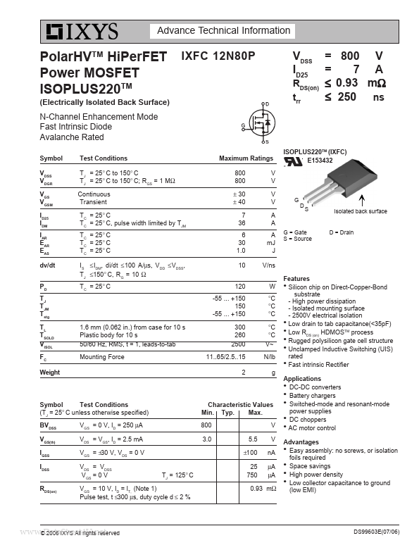
S
Isolated back surface
G = Gate S = Source
D = Drain
Symbol Test Conditions (TJ = 25° C unless otherwise specified) BVDSS VGS(th) IGSS IDSS RDS(on) VGS = 0 V, ID = 250 µA VDS = VGS, ID = 2.5 mA VGS = ±30 V, VDS = 0 V VDS = VDSS VGS = 0 V TJ = 125° C
Characteristic Values Min. Typ. Max....