FUS45-0045B Description
sine 180° (per diode) TC = 90°C (bridge) TVJ = 25°C; sine 50 Hz TC = 25°C (per diode) Maximum Ratings 45 V 20 A 45 A 150 A 40 W Symbol Conditions Characteristic Values (TVJ = 25°C, unless otherwise specified) min. TVJ = 25°C TVJ = 125°C IR VR = VRRM;.
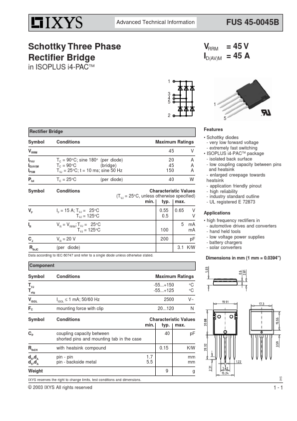
FUS45-0045B Key Features
- Schottky diodes
- very low forward voltage
- extremely fast switching
- ISOPLUS i4-PACTM package
- isolated back surface
- low coupling capacity between pins
- enlarged creepage towards heatsink
- application friendly pinout
- high reliability
- industry standard outline
FUS45-0045B Applications
- high frequency rectifiers in