ITC117PL
ITC117PL is Integrated Telecom Circuits manufactured by IXYS.
Features
- Current Limiting
- 3750Vrms Input/Output Isolation
- 2m W Hook Switch Drive Power (Logic patible)
- Full-Wave Bridge Rectifier
- Darlington Transistor for Electronic Inductor “Dry”
Circuits
- Full-Wave Current Detector for Ring Signal or Loop Current Detect
- JEDEC Standard Lead Configuration
- No Moving Parts
- Board Space and Cost Savings
- Small 16-Pin SOIC Package (PCMCIA patible)
Integrated Tele Circuits
Description
The Integrated Tele Circuit bines a single-pole, normally open (1-Form-A) solid state relay, a bridge rectifier, a Darlington transistor, and an optocoupler into one 16-pin SOIC package, consolidating designs and reducing ponent count in tele applications. The ITC117PL's relay features the added benefit of current limiting, and the optocoupler provides for fullwave detection of ring signals.
Approvals
- UL Recognized ponent: File E76270
- CSA Certified ponent: Certificate 1305490
- EN/IEC 60950-1 Certified ponent:
TUV Certificate: B 12 11 82667 002
Ordering Information
Part # ITC117PL ITC117PLTR
Description
16-Pin SOIC (50/Tube) 16-Pin SOIC (1000/Reel)
Applications
- Data/Fax Modem
- Voice Mail Systems
- Telephone Sets
- puter Telephony Integration
- Set Top Box Modems
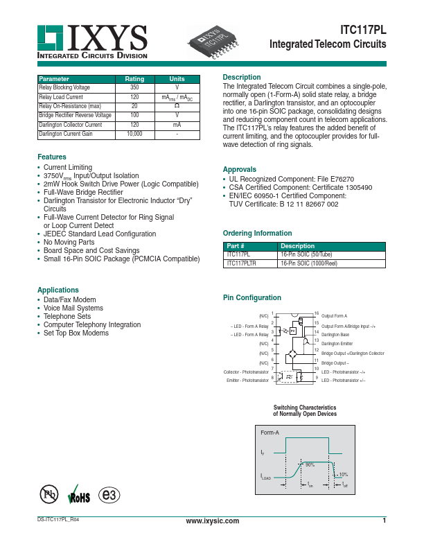
Pin Configuration
1 (N/C)
- LED
- Form A Relay
- LED
- Form A Relay
4 (N/C)
5...