IXFX64N50P
IXFX64N50P is Power MOSFET manufactured by IXYS.
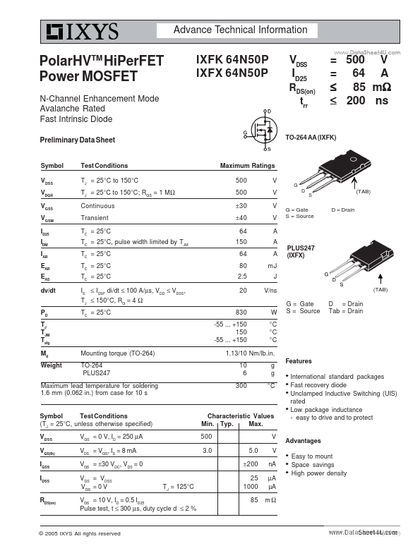
Features z z z
(TAB) D = Drain
G = Gate S = Source
PLUS247 (IXFX)
(TAB)
G = Gate S = Source
D = Drain Tab = Drain
Mounting torque (TO-264) TO-264 PLUS247
1.13/10 Nm/lb.in. 10 6 300 g g °C
Maximum lead temperature for soldering 1.6 mm (0.062 in.) from case for 10 s z
Symbol Test Conditions (TJ = 25°C, unless otherwise specified) VDSS VGS(th) IGSS IDSS RDS(on) VGS = 0 V, ID = 250 µA VDS = VGS, ID = 8 m A VGS = ±30 VDC, VDS = 0 VDS = VDSS VGS = 0 V TJ = 125°C
Characteristic Values Min. Typ. Max. 500 3.0 5.0 ±200 25 1000 85 V V n A µA µA mΩ
International standard packages Fast recovery diode Unclamped Inductive Switching (UIS) rated Low package inductance
- easy to drive and to protect
Advantages z z z
Easy to mount Space savings High power density
VGS = 10 V, ID = 0.5 ID25 Pulse test, t ≤ 300 µs, duty cycle d ≤ 2 %
© 2005 IXYS All rights reserved
DS99348(05/05)
IXFK 64N50P IXFX 64N50P
Symbol Test Conditions Characteristic Values (TJ = 25°C, unless otherwise specified) Min. Typ. Max. 30 50 8700 VGS = 0 V, VDS = 25 V, f = 1 MHz 970 90 30 VGS = 10 V, VDS = 0.5 VDSS, ID =0.5 ID25 RG = 2 Ω (External) 25 85 22 150 VGS = 10 V, VDS = 0.5 VDSS, ID = 0.5 ID25 50 50 0.15 0.15 S p F p F p F ns ns ns ns n C n C n C K/W K/W
Dim. A A1 A2 b b1 b2 C D E e L L1 Q R
Terminals: 1
- Gate 2
- Drain (Collector) 3
- Source (Emitter) 4
- Drain (Collector)
PLUS 247TM Outline
.. gfs Ciss Coss Crss td(on) tr td(off) tf Qg(on) Qgs Qgd Rth JC Rth CK
VDS = 20 V; ID = 0.5 ID25, pulse test
Source-Drain Diode Symbol IS ISM VSD t rr QRM IRM Test Conditions VGS = 0 V Repetitive
Characteristic Values (TJ = 25°C, unless otherwise specified) min. typ. max. 64 150 1.5 200 0.6 6.0 A A V ns µC A
Millimeter Min. Max. 4.83 5.21 2.29 2.54 1.91 2.16 1.14 1.40 1.91 2.13 2.92 3.12 0.61 0.80 20.80 21.34 15.75 16.13 5.45 BSC 19.81 20.32 3.81 4.32 5.59 6.20 4.32 4.83
Inches Min. Max. .190 .205 .090 .100 .075 .085 .045 .055 .075 .084 .115 .123 .024 .031 .819 .840 .620 .635 .215 BSC .780 .800...