IXYS IXGH32N60B
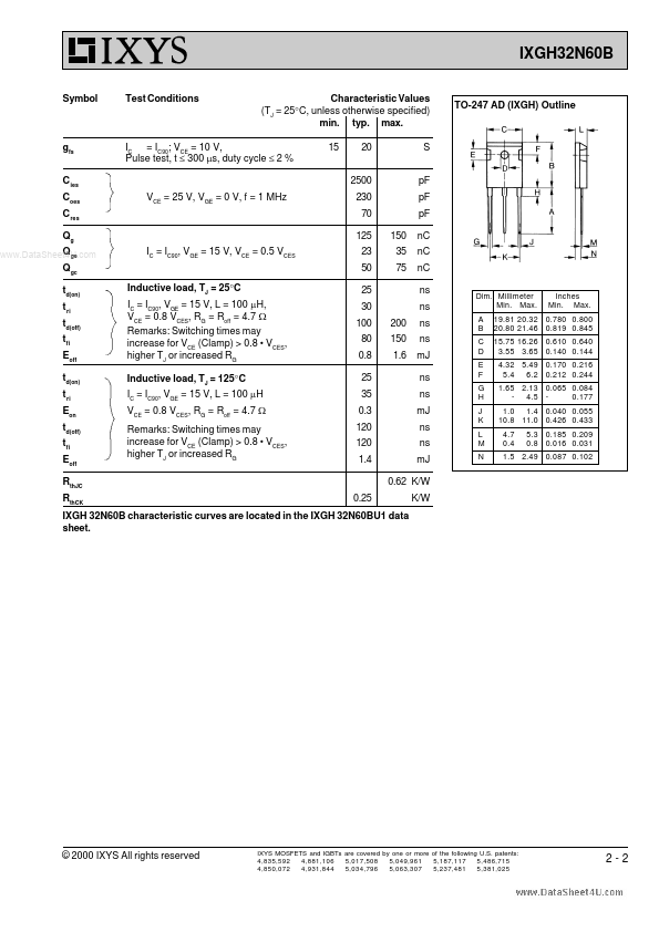
the IXGH 32N60BU1 data sheet.| Part No. | IXGH32N60B |
|---|---|
| Datasheet | IXGH32N60B Download |
| Manufacturer |  IXYS |
| Description | HiPerFAST IGBT |
| Buy | Stock & Price |

MAXIMUM RATINGS
600 600 ±20 ±30 60 32 120 ICM = 64 @ 0.8 VCES 200 -55 ... +150 150 -55 ... +150 300 V V V V A A A A W °C °C °C °C TO-247 AD C (TAB) G C E C = Collector, TAB = Collector G = Gate, E = Emitter,FEATURES
● International standard package JEDEC TO-247 AD● High current handling capability
● Newest generation HDMOSTM process
● MOS Gate turn-on - drive simplicity Maximum lead temperature for soldering 1.6 mm (0.062 in.) from case for 10 s Md Weight Mounting torque (M3) 1.13/10 Nm/lb.in. TO-247 AD 6 g
APPLICATIONS
Symbol Test Conditions Characteristic Values (TJ = 25°C, unless otherwise specified) min. typ. max. 600 2.5 TJ = 25°C TJ = 125°C V V mA mA nA V●
●
●
●
●
● PFC circuits AC motor speed control DC servo and robot drives DC choppers Uninterruptible power supplies (UPS) Switched-mode and resonant-mode power supplies BVCES VGE(th) ICES IGES VCE(sat) IC IC = 250 mA, VGE = 0 V = 250 mA, VCE = VGE 5 200 1 ±100 2.5 VCE = 0.8
● VCES VGE = 0 V VCE = 0 V, VGE = ±20 V IC = IC90, V...