Datasheet4U Logo Datasheet4U.com

IXGT20N140C3H1 - GenX3 1400V IGBTs

Key Features

  • z z z z z Optimized for Low Switching Losses Square RBSOA High Avalanche Capability Anti-Parallel Ultra Fast Diode International Standard Packages Advantages z z High Power Density Low Gate Drive Requirement Symbol Test Conditions (TJ = 25°C, Unless Otherwise Specified) VGE(th) ICES IGES VCE(sat) IC = 250μA, VCE = VGE TJ = 125°C, Note 1 VCE = 0V, VGE = ±20V IC = IC100, VGE = 15V, Note 1 TJ = 125°C VCE = VCES, VGE= 0V Characteristic Values Min. Typ. Max. 3.0 5.0 100 2.0 ±100 4.0 3.5 5.0 V μA.

📥 Download Datasheet

Full PDF Text Transcription (Reference)

The following content is an automatically extracted verbatim text from the original manufacturer datasheet and is provided for reference purposes only.

View original datasheet text
Advance Technical Information GenX3TM 1400V IGBTs w/ Diode High-Speed PT IGBTs for 20 - 50 kHz Switching IXGH20N140C3H1 IXGT20N140C3H1 VCES = IC100 = VCE(sat) ≤ tfi(typ) =
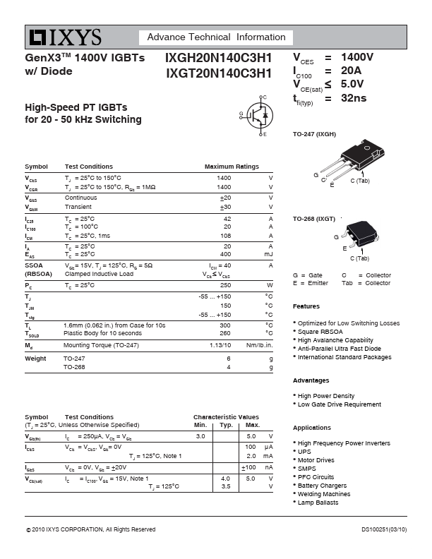
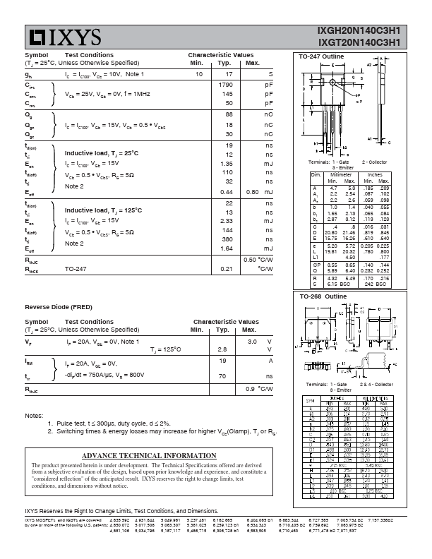
 TO-247 (IXGH) 1400V 20A 5.0V 32ns Symbol VCES VCGR VGES VGEM IC25 IC100 ICM IA EAS SSOA (RBSOA) PC TJ TJM Tstg TL TSOLD Md Weight Test Conditions TJ = 25°C to 150°C TJ = 25°C to 150°C, RGE = 1MΩ Continuous Transient TC = 25°C TC = 100°C TC = 25°C, 1ms TC = 25°C TC = 25°C VGE = 15V, TJ = 125°C, RG = 5Ω Clamped Inductive Load TC = 25°C Maximum Ratings 1400 1400 ±20 ±30 42 20 108 20 400 ICM = 40 VCE ≤ VCES 250 www.DataSheet.co.kr V V V V A A A A mJ A W °C °C °C °C °C Nm/lb.in. g g G C E C (Tab) TO-268 (IXGT) G E C (Tab) G = Gate E = Emitter C = Collector Tab = Collector -55 ... +150 150 -55 ... +150 1.