IXTP4N65X2 Description
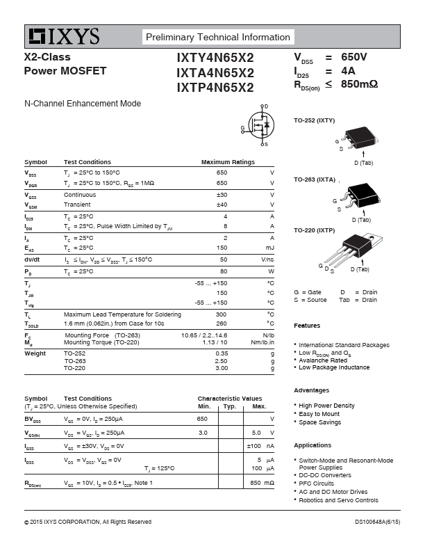
Preliminary Technical Information X2-Class Power MOSFET N-Channel Enhancement Mode IXTY4N65X2 IXTA4N65X2 IXTP4N65X2 VDSS = ID25 = RDS(on) 650V 4A 850m TO-252 (IXTY) Symbol VDSS VDGR VGSS VGSM ID25 IDM IA EAS dv/dt PD TJ TJM Tstg TL TSOLD FMCd Weight Test.
IXTP4N65X2 Key Features
- International Standard Packages
- Low RDS(ON) and QG
- Avalanche Rated
- Low Package Inductance
- ID25, Note 1
- High Power Density
- Easy to Mount
- Space Savings