Datasheet4U.com
🌙
MUBW15-06A7 Datasheet | IXYS
Part:
MUBW15-06A7
Description:
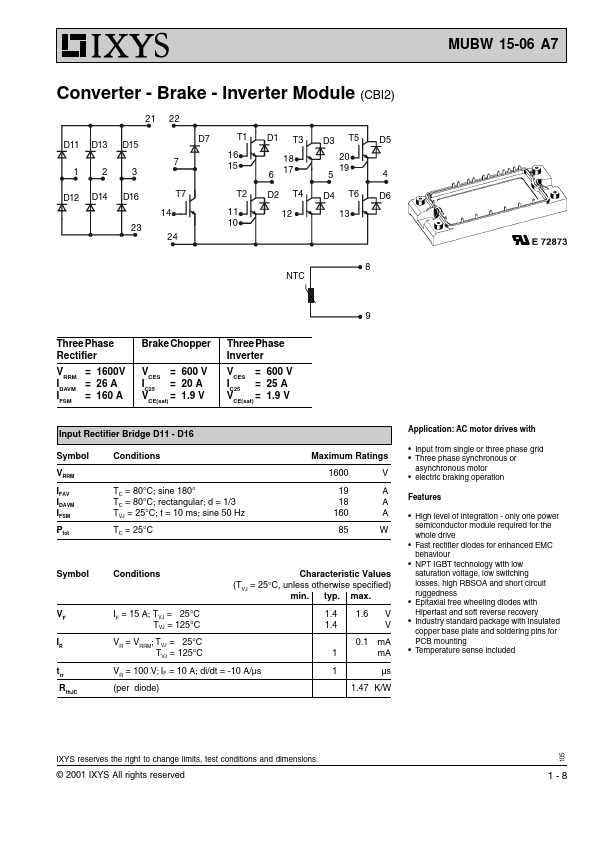
Converter - Brake - Inverter Module
Manufacturer:
IXYS
Size:
186.64 KB
MUBW15-06A7 Datasheet (PDF) Download
Related MUBW15-06A7 Datasheets
MUBW15-06A6K Converter - Brake - Inverter Module
MUBW15-06A6 Converter - Brake - Inverter Module
IXYS
MUBW15-06A7
Key Features
q High level of integration - only one power semiconductor module required for the whole drive
×
Close