IXYS VDI25-06P1
IGBT Modules
| Part No. | VDI25-06P1 |
|---|---|
| Datasheet | VDI25-06P1 Download |
| Manufacturer |  IXYS |
| Description | IGBT Modules |
| Buy | Stock & Price |
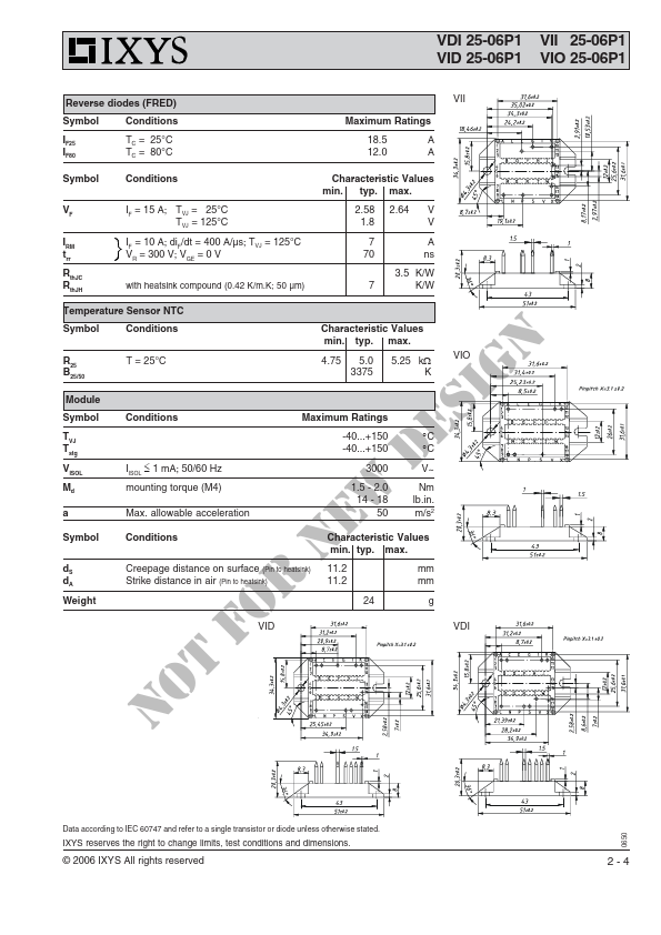
MAXIMUM RATINGS
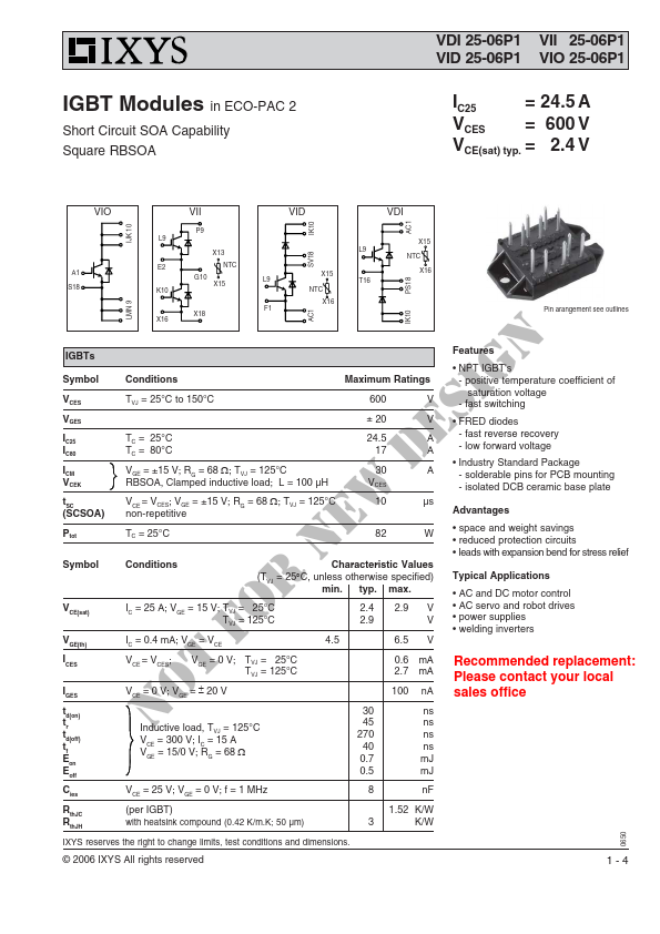
TVJ = 25°C to 150°C 600 ± 20 V V TC = 25°C TC = 80°C VGE = ±15 V; RG = 68 Ω; TVJ = 125°C RBSOA, Clamped inductive load; L = 100 µH VCE = VCES; VGE = ±15 V; RG = 68 Ω; TVJ = 125°C non-repetitive 24.5 17 30 VCES 10 A A A µs TC = 25°C 82 W Symbol Conditions Characteristic Values (T = 25°C, unless otherwise specified) VJ min. typ. max. VCE(sat) IC = 25 A; VGE = 15 V; TVJ = 25°C TVJ = 125°C 2.4 2.9 VGE(th) IC = 0.4 mA; VGE = VCE 4.5 I CES V =V ; CE CES V = 0 V; GE TVJ = 25°C TVJ = 125°C IGES VCE = 0 V; VGE = ± 20 V td(on) tr td(off) t f Eon E off Inductive load, TVJ = 125°C VCE = 300 V; IC = 15 A V = 15/0 V; R = 68 Ω GE G 30 45 270 40 0.7 0.5 Cies VCE = 25 V; VGE = 0 V; f = 1 MHz 8 RthJC RthJH (per IGBT) with heatsink compound (0.42 K/m.K; 50 µm) 3 IXYS reserves the right to change limits, test conditions and dimensions. 2.9 V V 6.5 V 0.6 mA 2.7 mA 100 nA ns ns ns ns mJ mJ nF 1.52 K/W K/W © 2006 IXYS All rights reservedFEATURES
● NPT IGBT's - positive temperature coefficien...