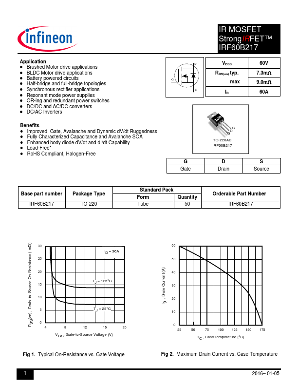
IRF60B217
IRF60B217 is IR MOSFET manufactured by Infineon.
Application
- Brushed Motor drive applications
- BLDC Motor drive applications
- Battery powered circuits
- Half-bridge and full-bridge topologies
- Synchronous rectifier applications
- Resonant mode power supplies
- OR-ing and redundant power switches
- DC/DC and AC/DC converters
- DC/AC Inverters
D
Benefits
- Improved Gate, Avalanche and Dynamic dV/dt Ruggedness
- Fully Characterized Capacitance and Avalanche SOA
- Enhanced body diode dV/dt and dI/dt Capability
- Lead-Free-
- RoHS pliant, Halogen-Free
G Gate
IR MOSFET StrongIRFET™ IRHEFXF6E0TB® P2o1we7r MOSFET
VDSS RDS(on) typ. max ID
60V 7.3m 9.0m
60A
S D G TO-220AB IRF60B217
D Drain
S Source
Base part...