Infineon Technologies IRF60R217
IR MOSFET
| Part No. | IRF60R217 |
|---|---|
| Datasheet | IRF60R217 Download |
| Manufacturer |  Infineon Technologies |
| Description | IR MOSFET |
| Buy | Stock & Price |
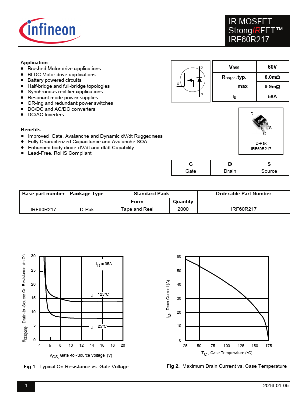
ELECTRICAL CHARACTERISTICS
@ TJ = 25°C (unless otherwise specified) Symbol gfs Qg Qgs Qgd Qsync td(on) tr td(off) tf Ciss Coss Crss Coss eff.(ER) Coss eff.(TR) Parameter Forward Transconductance Total Gate Charge Gate-to-Source Charge Gate-to-Drain Charge Total Gate Charge Sync. (Qg– Qgd) Turn-On Delay Time Rise Time Turn-Off Delay Time Fall Time Input Capacitance Output Capacitance Reverse Transfer Capacitance Effective Output Capacitance (Energy Related) Output Capacitance (Time Related) Min. 120 ––– ––– ––– ––– ––– ––– ––– ––– ––– ––– ––– ––– ––– Typ. ––– 40 10 12 28 7.6 29 21 12 2170 210 130 228 283 Max. Units Conditions ––– S VDS = 10V, ID = 35A 66 ID = 35A ––– ––– nC VVDGSS = = 30V 10V ––– ––– VDD =30V ––– ––– ns ID = 35A RG= 2.7 ––– VGS = 10V ––– VGS = 0V ––– VDS = 25V ––– pF ƒ = 1.0MHz, See Fig. 7 ––– VGS = 0V, VDS = 0V to 48V ––– VGS = 0V, VDS = 0V to 48V Diode Characteristics Symbol IS ISM Parameter Continuous Source Current (Body Diode) Pulsed Source Current (Body Diode) Min. ––– ––– Typ. ––– ––– Max.
