Integral IL8560
The on-chip Schmitt trigger circuit allows a simple RC filter at the input to remove possible line voltage transients. The values of CR determine the frequency of the on-chip clock oscillator.| Part No. | IL8560 |
|---|---|
| Datasheet | IL8560 Download |
| Manufacturer |  Integral |
| Description | CLOCK CIRCUIT |
| Buy | Stock & Price |
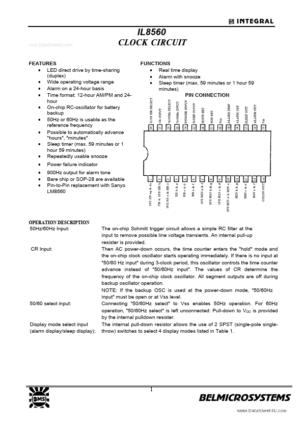
FEATURES
● LED direct drive by time-sharing (duplex)● Wide operating voltage range
● Alarm on a 24-hour basis
● Time format: 12-hour AM/PM and 24hour
● On-chip RC-oscillator for battery backup
● 50Hz or 60Hz is usable as the reference frequency
● Possible to automatically advance "hours", "minutes"
● Sleep timer (max. 59 minutes or 1 hour 59 minutes)
● Repeatedly usable snooze
●
●
●
● Power failure indicator 900Hz output for alarm tone Bare chip or SOP-28 are available Pin-to-Pin replacement with Sanyo LM8560 OPERATION
DESCRIPTION
50Hz/60Hz Input: CR Input: 50/60 select input: Display mode select input (alarm display/sleep display); An internal pull-up resister is provided. Then AC power-down occurs, the time counter enters the "hold" mode and the on-chip clock oscillator starts operating immediately. If there is no input at "50/60 Hz input" during 3-clock period, this oscillator controls the time counter advance instead of "50/60Hz input". All segment outputs are off during backup oscillator operation.